DMS-40PC-3-RS-C Murata Power Solutions Inc, DMS-40PC-3-RS-C Datasheet - Page 4
DMS-40PC-3-RS-C
Manufacturer Part Number
DMS-40PC-3-RS-C
Description
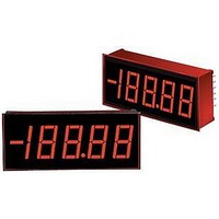
DC Miniature Digital Voltage Meter
Manufacturer
Murata Power Solutions Inc
Datasheet
1.DMS-40PC-3-RS-C.pdf
(6 pages)
Specifications of DMS-40PC-3-RS-C
No. Of Digits / Alpha
4-1/2
Meter Function
DC Voltmeter
Meter Range
± 0V To ± 200V
Digit Height
13.2mm
Power Consumption
500mW
Operating Temperature Range
0°C To +50°C
Accuracy
±2
Display Type
4 - 1/2 Digit LED
Sample Rate
2.5 SPS
Rohs Compliant
Yes
Lead Free Status / RoHS Status
Lead free / RoHS Compliant


2. Differential Input Confi gurations: Differential inputs can also be
3. Power Supply Monitoring: One of the most widely used digital panel
APPLICATIONS
measured with DMS-40PC meters as shown in the circuit of Figure
3. Differential inputs must also originate from power supplies that
have a common ground with the meter’s 5V RETURN (pin 3). However,
differential inputs usually have both terminals above and/or below
5V RETURN. Figure 3, though not necessarily a typical real-world
application, does serve the purpose of illustrating the concept of a
differential signal.
The voltages developed across R1, R2 and R3 are equal to each other
and measure approximately +1.6666Vdc or 1/3 of the +5V power
source. More importantly, while the signal across R3 is single-ended,
both ends of R1 and R2 are well above ground and are described
here as being differential. Please note that while the DMS-40PC can
measure the voltages across either R2 or R3, it cannot measure
the +1.6666 volts across R1! The voltage at the lower end of R1 is
approximately 3.333V and this exceeds the common mode voltage
limit of ±2V.
voltmeter applications is monitoring the output voltage of a system
power supply — often the same supply that also powers the meter.
The low-power, red LED DMS-40PC-2-RL, with its excellent 0.001Vdc
resolution, can be confi gured to monitor power supplies with outputs
in the range of 4.5-18Vdc. The circuit in Figure 4 uses a low-drop-
out, three-terminal regulator (LM-2931T-5, in a T0-220 package,
available from National Semiconductor) to provide regulated 5V
power to the meter.
The LM-2931 was chosen because it has the following on-chip pro-
tection features: reverse polarity, short circuit and thermal runaway.
The DMS-40PC-3-RL can monitor voltages up to ±200Vdc, provided
a separate +5V power source is used since many three-terminal
regulators cannot operate with supply voltages greater than 24V. Red,
low-power LED models, with their very low self-heating, are recom-
mended for applications in which low calibration drift is desirable.
120 VAC
AC to DC Converter
DP1
Figure 3. Differential Input Confi guration
+5V SUP
1
DMS-40PC-1-GS
5V RET
3
12
11
(+) IN HI
(–) IN LO
www.murata-ps.com/dpm
R1
1k
R2
1k
R3
1k
4. Floating Signal Source Measurements: A fl oating input is a signal
that, before it is applied to the DMS-40PC’s inputs, has no galvanic
connection (direct current path) to the meter or the meter’s power
supply. The circuit shown in Figure 5 illustrates the necessary con-
nections for measuring fl oating inputs. The 1.5V battery represents a
true fl oating input signal since it initially has no connection whatso-
ever in common with the meter. Real-world fl oating inputs typically
originate from power supplies which are transformer isolated from
the DMS-40PC’s +5V supply.
The connection of pin 12 ((–) INPUT LO) to pin 10 (ANALOG COMMON)
is required in order to provide a bias return for the meter’s input
amplifi er. This is because neither pin 11 nor pin 12 are tied to any
reference voltage inside the DMS-40PC (see Figure 1). These connec-
tions are not made internally in order to give the meter the ability to
make differential measurements as described in a previous section.
When using other, higher-power, DMS-40PC models in combina-
tion with three-terminal regulators, be sure to consult the regulator
manufacturer’s data sheet to ensure the device is being utilized safely
and correctly.
+
–
4½ Digit, LED Display Digital Panel Voltmeters
4.5 - 18Vdc
CELL
1.5V
120 VAC
–
LM2931T-5
IN
AC to DC Converter
Figure 4. 4.5-18V Power Supply Monitor
GND
Figure 5. Floating Input Measurements
OUT
ANA COMM
(–) IN LO
22μF
10V
(+) IN HI
+
12
DMS-40PC Series
11
10
+5V SUP
04/05/11 MPM_DMS-40PC.C05 Page 4 of 6
+5V SUP
5V RET
DP2
1
1
3
5
(+) IN HI
DMS-40PC-1-GS
5V RET
11
email: sales@murata-ps.com
(–) IN LO
12
3
DMS-40PC-2-RL
DP1
6
Related parts for DMS-40PC-3-RS-C
Image
Part Number
Description
Manufacturer
Datasheet
Request
R

Part Number:
Description:
DPM ±2V 4.5 Dig Yel LED
Manufacturer:
Murata Power Solutions Inc
Datasheet:
Part Number:
Description:
DPM ±2V 4.5 Dig Red LED
Manufacturer:
Murata Power Solutions Inc
Datasheet:
Part Number:
Description:
DPM ±20V 4.5 Dig Red LED
Manufacturer:
Murata Power Solutions Inc
Datasheet:
Part Number:
Description:
DPM ±20V 4.5 Dig Red LED
Manufacturer:
Murata Power Solutions Inc
Datasheet:
Part Number:
Description:
DPM ±20V 4.5 Dig Red LED
Manufacturer:
Murata Power Solutions Inc
Datasheet:
Part Number:
Description:
DPM ±20V 4.5 Dig Yel LED
Manufacturer:
Murata Power Solutions Inc
Datasheet:
Part Number:
Description:
DPM ±200V 4.5 Dig Grn LED
Manufacturer:
Murata Power Solutions Inc
Datasheet:
Part Number:
Description:
DPM ±200V 4.5 Dig Red LED
Manufacturer:
Murata Power Solutions Inc
Datasheet:
Part Number:
Description:
DPM ±200V 4.5 Dig Red LED
Manufacturer:
Murata Power Solutions Inc
Datasheet:
Part Number:
Description:
DPM ±200V 4.5 Dig Red LED
Manufacturer:
Murata Power Solutions Inc
Datasheet:

Part Number:
Description:
Digital Panel Meters DMS-20 BezelAssembly Panel mount
Manufacturer:
Murata Power Solutions Inc
Datasheet:

Part Number:
Description:
DPM LED MINI 2VDC 3.5DIG LP RED
Manufacturer:
Murata Power Solutions Inc
Datasheet:

Part Number:
Description:
DPM LED 2VDC 4.5DIGIT GREEN
Manufacturer:
Murata Power Solutions Inc
Datasheet:

Part Number:
Description:
DPM LED 2VDC 3.5DIGIT LP RED
Manufacturer:
Murata Power Solutions Inc
Datasheet:

Part Number:
Description:
Transformers 5Vin 5Vout 200mA 4000Vdc 1:1.33 turn
Manufacturer:
Murata Power Solutions Inc
Datasheet: