IDC15 OPTO 22, IDC15 Datasheet - Page 2
IDC15
Manufacturer Part Number
IDC15
Description
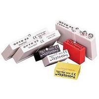
I/O Module
Manufacturer
OPTO 22
Type
Inputr
Specifications of IDC15
Peak Reflow Compatible (260 C)
No
Signal Input Type
10 To 32VAC
No. Of Outputs
1
No. Of Analog Inputs
1
No. Of Digital Outputs
1
Connection To Host
Backplane
Current Rating
50 mA
Current, Input
15 mA
Dimensions
43.2mmL×15.2mmW×31.8mmH
Input
10 to 32 VDC
Input Type
Digital
Input, Range
10 to 32 VDC
Logic Voltage, Nominal
5 VDC
Mounting Type
PCB
Primary Type
Data Acquisition
Special Features
Optical Isolation
Temperature, Operating, Maximum
70 °C
Temperature, Operating, Minimum
-30 °C
Time, Turn-off
5 ms
Time, Turn-on
5 ms
Voltage, Isolation
4000 V
Voltage, Logical
5 VDC
Voltage, Rating
12 to 32 VDC
Voltage, Supply
15 VDC
Lead Free Status / RoHS Status
Lead free / RoHS Compliant


PAGE
2
Module Specifications
General
DC Input Module Specifications
Opto 22 • 43044 Business Park Drive • Temecula, CA 92590-3614 • www.opto22.com
SALES 800-321-6786 • 951-695-3000 • FAX 951-695-3095 • sales@opto22.com • SUPPORT 800-835-6786 • 951-695-3080 • FAX 951-695-3017 • support@opto22.com
© 2006 Opto 22. All rights reserved. Dimensions and specifications are subject to change. Brand or product names used herein are trademarks or registered trademarks of their respective companies or organizations.
Operating Ambient Temperature
Isolation, Input-to-Output (Transient)
Output Voltage Drop: logic side
Output Current
Output Leakage With No Input
Transistor
Input Voltage Range
Input Current @ Max Line
Turn-on Time
Turn-off Time
Input Allowed for No Output
Output Supply
Voltage-Nominal
Output Supply
Voltage-Range
Output Supply Current
@ Nominal Logic Voltage
Input Resistance
Control Resistance
(Rc in schematic diagram)
Input Voltage Range
Input Current @ Max Line
Turn-on Time
Turn-off Time
Input Allowed for No Output
Output Supply
Voltage-Nominal
Output Supply
Voltage-Range
Output Supply Current
@ Nominal Logic Voltage
Input Resistance
Control Resistance
(Rc in schematic diagram)
IDC5D Only
Ohms
Ohms
Ohms
Ohms
msec
msec
msec
msec
Volts
VDC
Volts
VDC
VDC
VDC
VDC
VDC
Unit
VAC
Unit
VAC
mA
mA
mA
mA
mA
mA
- 30 to 70 °C
4000 V
0.4 volts @ 50 mA
50 mA
0.1 mA @ 30 VDC
0.01 mA @ 30 VDC
30 volts breakdown
90–140
90–140
10–32
12–32
4.5–6
4.5–6
IDC5
IAC5
1.5k
220
28k
220
25
12
20
20
45
12
5
3
5
5
5
1
3
5
90–140
90–140
IDC5B
IAC15
12–18
4.5–6
4–16
4–16
0.05
300
220
28k
0.1
0.7
20
20
45
15
15
45
12
1k
1
5
5
3
Standard DC Input Modules
90–140
90–140
IDC5D
2.5–28
IAC24
20–30
4.5–6
2.2k
900
470
28k
1.5
0.2
30
12
20
20
45
24
18
—
1
1
5
5
3
180–280
180–280
IDC5G
IAC5A
35–60
35–60
4.5–6
4.5–6
10k
220
70k
220
0.7
20
20
45
12
10
10
12
5
1
5
6
7
5
180–280
180–280
IAC15A
IDC15
12–18
10–32
12–32
12–18
1.5k
70k
25
15
15
20
20
45
15
15
1k
1k
5
5
1
3
5
1
180–280
180–280
IAC24A
IDC24
10–32
12–32
20–30
20–30
1.5k
2.2k
2.2k
70k
25
24
18
20
20
45
24
15
5
1
5
5
1
3
Related parts for IDC15
Image
Part Number
Description
Manufacturer
Datasheet
Request
R

Part Number:
Description:
SSR, PANEL MOUNT, 280VAC, 32VDC, 10A
Manufacturer:
OPTO 22
Datasheet:

Part Number:
Description:
SSR, PANEL MOUNT, 280VAC, 32VDC, 25A
Manufacturer:
OPTO 22
Datasheet:
Part Number:
Description:
SSR, PANEL MOUNT, 280VAC, 32VDC, 25A
Manufacturer:
OPTO 22
Datasheet:
Part Number:
Description:
SSR, PANEL MOUNT, 280VAC, 32VDC, 45A
Manufacturer:
OPTO 22
Datasheet:
Part Number:
Description:
SSR, PANEL MOUNT, 280VAC, 32VDC, 45A
Manufacturer:
OPTO 22
Datasheet:

Part Number:
Description:
SSR, 10A, 240VAC
Manufacturer:
OPTO 22
Datasheet:

Part Number:
Description:
Programmable Logic Controller
Manufacturer:
OPTO 22
Datasheet:

Part Number:
Description:
Programmable Logic Controller
Manufacturer:
OPTO 22
Datasheet:

Part Number:
Description:
Solid State Relays, Accessories
Manufacturer:
OPTO 22
Datasheet:
