SMARTSTART-BDC-D IDEC, SMARTSTART-BDC-D Datasheet - Page 3
SMARTSTART-BDC-D
Manufacturer Part Number
SMARTSTART-BDC-D
Description
Programmable Logic Controller
Manufacturer
IDEC
Datasheet
1.FL1B-M08D2R2.pdf
(14 pages)
Specifications of SMARTSTART-BDC-D
For Use With
FL1D-B12RCE
Lead Free Status / RoHS Status
Lead free / RoHS Compliant


Base Module Part Number
Expansion Module Part Number
Starter Kit Part Number
Accessories
www.idec.com
Part Number
FL1C-H12RCE
FL1C-B12RCE
FL1C-H12SND
FL1C-H12RCA
FL1C-B12RCA
FL1C-H12RCC
FL1C-B12RCC
Part No.
FL1B-M08B2R2
FL1B-M08B1S2
FL1B-M08C2R2
FL1B-M08D2R2
FL1B-J2B2
FL1B-CL1C12
FL1B-CAS2
Part Number
SMARTSTART-BAC-C
SMARTSTART-BDC-C
SMARTSTART-HAC-C
SMARTSTART-HDC-C
Part Number
FL1C-PM3
FL9Y-LP1CDW
FL1A-PC1
BAA1000
BNDN1000
BNL6
MT-101
FL1B-PSP1
FL1B-Y1371-SW8
FL9Y-B827
FC4A-USB
* For more information see Section M, Communications & Networking.
Rated Voltage
12/24V DC
24V DC
24V AC/DC
100-240V AC/DC
IDEC SmartRelay
Module
Combination I/O Module
Analog Input Module
L
AS-Interface Communication Module*
Description
Memory Cartridge
Programming Software: WindLGC Ver. 4
PC Interface Cable
35MM DIN Rail
Mounting Clips
Memory Cartridge Removal Tool
Direct Mounting Slides
8pt simulator switch
FL1C user’s manual
USB/RS232 converter
ON
Description
FL1C-B12RCC, WindLGC software, and programming cable
FL1C-B12RCE, WindLGC software, programming cable, and simulator switch
FL1C-H12RCC, WindLGC software, and programming cable
FL1C-H12RCE, WindLGC software, programming cable, and simulator switch
W
ORKS ®
Communication Module*
Input Signal
DC
I7and I8 are used
for digital/analog
AC/DC
USA: (800) 262-IDEC or (408) 747-0550, Canada: (888) 317-IDEC
Aluminum, 1m/3.28ft
Input Type
PNP
PNP/NPN
PNP
Power Voltage
12/24V DC
24V DC
100-240V AC/DC
24V AC/DC
12/24V DC
24V AC/DC
30V DC
Part Numbers
Note
Memory cartridge with know-how protection
CD w/Online Manual
Connection of SmartRelay to PC
used with 12, 24V DC base module only
Output Signal
Relay Output
Transistor Source Output
Relay Output
Input
DC input
DC input
AC/DC input
AC/DC input
Analog input
–
_
Output
Relay output
Transistor output
Relay output
Relay output
–
–
_
With Display With Clock
Yes
—
Yes
Yes
—
Yes
—
Yes
—
Yes
8 (4 in/4 out)
8 (4 in/4 out)
8 (4 in/4 out)
8 (4 in/4 out)
2 (2 in/0 out)
_
Total I/O
–
Selection Guide
Input/Output
8/4
H-3
H
Related parts for SMARTSTART-BDC-D
Image
Part Number
Description
Manufacturer
Datasheet
Request
R

Part Number:
Description:
Programmable Logic Controller
Manufacturer:
IDEC
Datasheet:
Part Number:
Description:
Programmable Logic Controller
Manufacturer:
IDEC
Datasheet:
Part Number:
Description:
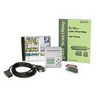
SMARTRELAY STARTER KIT
Manufacturer:
IDEC
Datasheet:
Part Number:
Description:
SMARTRELAY STARTER KIT
Manufacturer:
IDEC
Datasheet:
Part Number:
Description:
SMARTRELAY STARTER KIT
Manufacturer:
IDEC
Datasheet:

Part Number:
Description:
FL1E SMARTRELAY STARTER KIT 120-240VAC/DC BASE MODULE W/O LCD DISPLAY
Manufacturer:
IDEC Corporation
Datasheet:
Part Number:
Description:
Cable; Between IDEC MicroSmart (port 1 or 2) and HG2F/3F/4F; 5 ft.
Manufacturer:
IDEC Corporation
Datasheet:
Part Number:
Description:
Cable; Between IDEC Micro^3C/ONC/MicroSmart (port 2) PLCs and HG2F/3F/4F; 5 ft.
Manufacturer:
IDEC Corporation
Datasheet:
Part Number:
Description:
Angled Key for Idec HS6B Safety Switch
Manufacturer:
IDEC Corporation
Datasheet:

Part Number:
Description:
JACK PANEL MOUNT SMA
Manufacturer:
Samtec Inc
Datasheet:
Part Number:
Description:
INDICATOR INCANDESCENT LAMP, GREEN
Manufacturer:
IDEC
Datasheet:

Part Number:
Description:
LAMP, INDICATOR, INCAND, AMB
Manufacturer:
IDEC
Datasheet:
Part Number:
Description:
LAMP, INDICATOR, INCAND, GRN
Manufacturer:
IDEC
Datasheet:
Part Number:
Description:
LAMP, INDICATOR, INCAND, GRN
Manufacturer:
IDEC
Datasheet: