H7AN-4D-AC100-240 Omron, H7AN-4D-AC100-240 Datasheet - Page 14
H7AN-4D-AC100-240
Manufacturer Part Number
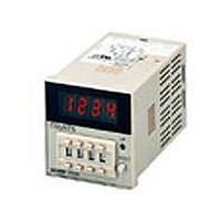
H7AN-4D-AC100-240
Description
COUNTER DIGITAL LED
Manufacturer
Omron
Datasheet
1.H7AN-RT8-AC100-240.pdf
(20 pages)
Specifications of H7AN-4D-AC100-240
Rohs Compliant
YES
Digit Height
72mm
Supply Voltage Range
100VAC To 240VAC
Counting Speed
30Hz
Operating Temperature Range
-10°C To +55°C
No. Of Digits / Alpha
4
Lead Free Status / Rohs Status
Lead free / RoHS Compliant


Mounting
Mounting brackets are included with the H7AN. Use these brackets to mount the H7AN securely so that there is no play.
Installation
■ Terminal Arrangement
■ Connections
Solid-state Inputs (NPN Transistors)
The CP1, CP2, and reset inputs of the H7AN must be voltage inputs.
Turn the screws on the mounting
brackets counterclockwise to
loosen them sufficiently. Attach
the bottom mounting bracket first.
1-stage Preset Counters
Total Counters
Power supply input
Power supply input
0 V
0 V
8
1
8
1
Power supply circuit
Power supply circuit
Surge
absorber
Surge
absorber
(−)
(−)
Input
resis-
tance
4.7 kΩ
Input
resis-
tance
4.7 kΩ
Reset
input
Reset
input
9
2
9
2
CP2
input
Input
resis-
tance
4.7 kΩ
Input
resis-
tance
4.7 kΩ
CP2
input
10
3
10
3
Ground terminal
Ground terminal
Input
resis-
tance
4.7 kΩ
CP1
input
Input
resis-
tance
4.7 kΩ
CP1
input
Contact output
11
4
11
4
External
power
supply
(12 V)
External
power
supply
(12 V)
12 V
12 V
Open terminals
12
5
12
5
1.5 kΩ
(+)
(+)
Open terminals
After attaching the mounting brackets,
turn the screws clockwise to tighten
them sufficiently. When the screws are
completely tightened, you will hear the
threads disengage.
13
6
13
6
Solid-state
output
Open terminal
14
7
14
7
Note: 1. The polarities of the DC power supply terminals are as
2-stage Preset Counters
Power supply input
0 V
2. If there is excessive external noise, terminal 3 must be
3. The open terminals cannot be used as relay terminals.
4. Insert surge absorbers between each of the power
8
1
Power supply circuit
Surge
absorber
(−)
follows:
Terminal 1: negative; terminal 2: positive
grounded to an appropriate place where the grounding
resistance is 100 Ω max. There will be a current leakage
of 0.2 mA each from terminals 1 and 2 to terminal 3.
supply terminals and the ground terminal. If the ground
terminal is not used, insert the surge absorbers between
terminal 1 and terminal 2.
Input
resis-
tance
4.7 kΩ
Reset
input
9
2
Input
resis-
tance
4.7 kΩ
CP2
input
10
3
Ground terminal
Input
resis-
tance
4.7 kΩ
CP1
input
11
2nd output
4
External
power
supply
(12 V)
12 V
Contact output
12
5
1.5 kΩ
2nd output
(+)
13
6
1st output
Solid-state
output
1.5 kΩ
1st output
14
7
H7AN
14
Related parts for H7AN-4D-AC100-240
Image
Part Number
Description
Manufacturer
Datasheet
Request
R

Part Number:
Description:
G6S-2GLow Signal Relay
Manufacturer:
Omron Corporation
Datasheet:
Part Number:
Description:
Compact, Low-cost, SSR Switching 5 to 20 A
Manufacturer:
Omron Corporation
Datasheet:
Part Number:
Description:
Manufacturer:
Omron Corporation
Datasheet:
Part Number:
Description:
Manufacturer:
Omron Corporation
Datasheet:
Part Number:
Description:
Manufacturer:
Omron Corporation
Datasheet:
Part Number:
Description:
Manufacturer:
Omron Corporation
Datasheet:
Part Number:
Description:
Manufacturer:
Omron Corporation
Datasheet:
Part Number:
Description:
Manufacturer:
Omron Corporation
Datasheet: