CUB4I000 Red Lion Controls, CUB4I000 Datasheet - Page 4
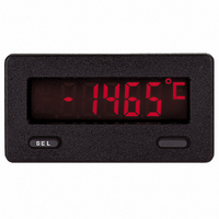
CUB4I000
Manufacturer Part Number
CUB4I000
Description
DC Current Meter, Reflective Display
Manufacturer
Red Lion Controls
Series
CUB4r
Type
Ammeterr
Datasheet
1.CUB4V000.pdf
(8 pages)
Specifications of CUB4I000
Measuring Range
0 ~ 199.9mA
Display Style
Black Characters, Grey Background
Display Type
LCD
Display Face Size
2.95" L x 1.54" W (74.9 x 39.1mm)
Display Digits
3.5
Display Digits - Height
0.600" (15.24mm)
Backlight
Without
Mounting Type
Panel Mount
Termination
Screw Terminals
Voltage - Supply
9 ~ 28VDC
Accuracy
±0.1% (199.9 µA to 19.99 mA)
Application
Used in Industrial Environments
Bezel
NEMA 4X⁄IP65 Sealed Front Panel
Brand/series
CUB
Connection Type
Screw-Clamp
Current, Rating
±199.9 mAdc (Max.)
Cut Out, Panel
2.68×1.3 "
Digit Height
0.6
Dimensions
2.95"L×2.11"W×1.54"H
Display Digit Height
0.6 "
Function
Ammeter
Humidity
85% (Max.) @ 60 °C (Non-Condensing)
Indicator Type
3-1⁄2 Digit
Material, Casing
Plastic
Meter Type
DC Current
Number Of Digits
3-1/2
Primary Type
Electronic
Range, Measurement
±199.9 μADC to ±199.9 mADC
Special Features
programmable
Standards
cULus Recognized
Temperature, Operating
0 to 60 °C
Voltage, Supply
9 to 28 VDC
Panel Cutout
2.68" × 1.30"
Lead Free Status / RoHS Status
Lead free / RoHS Compliant
Lead Free Status / RoHS Status
Lead free / RoHS Compliant
Other names
Q1156337


VOLTMETER SCALING
in terms of PSI, RPM, or some other unit of measure. The signal voltage being
measured is normally generated by a transducer which senses the variable and
delivers a linear output voltage. To provide the desired readout at the specified
voltage, the voltmeter must be scaled. The Scale switch, when in the “ON”
position, enables the Scale Potentiometer. The Scale Potentiometer is used with
a voltage range to provide a method of scaling the unit. The voltage DIP
switches are used to select one of the four coarse Division Factor ranges and the
Scale Potentiometer is a fine scale adjustment within the selected range. The
chart below shows the division factor range associated with each range
selection switch.
Note: Enabling the Scale Potentiometer does NOT affect the calibration of
the “Division Factor” required to provide the proper display reading must first
be determined by using the following formula.
WHERE:
voltage range switch that will provide for the Division Factor is set to the “ON”
position. Use the “Division Factor Range Selection Chart” to choose the proper
DIP switch setting.
Note: Only one voltage DIP switch should be turned on. Set the switch before
EXAMPLE: A relative humidity transducer delivers a 7.0 VDC voltage at a
position S3 is set to the “ON” position. The Scaling Potentiometer is then
adjusted for the desired readout at a known relative humidity.
In many industrial applications, a voltmeter is required to display a reading
the unit.
To determine the proper voltage range for an application requiring scaling,
After the Division Factor for the application has been calculated, the proper
the voltage signal is applied.
relative humidity of 75%.
This Division Factor is between 10.5 and 100.5, therefore DIP switch
VT
D.D.P. =
D.F.
D.R.
D.D.P.
0.000
00.00
000.0
0000
=
=
=
=
=
=
=
Maximum Transducer Output
Display Decimal Point
Division Factor
Desired Reading
1
10
100
1000
DIVISION FACTOR RANGE SELECTION CHART
D.F. = VT x D.D.P. = 7.0 x 1000 = 93.3
S1: 0-199.9 mVDC (0.1 D.F. 1.2)
S2: 0-1.999 VDC (1.2 D.F. 10.5)
S3: 0-19.99 VDC (10.5 D.F. 100.5)
S4: 0-199.9 VDC (100.5 D.F. 1300)
BLOCK DIAGRAM CUB4V
The DISPLAY DECIMAL POINT (D.D.P.)
is determined by the desired decimal
point placement in the readout.
USING THE FORMULA:
D.F = VT x D.D.P.
D.R.
D.R.
75
4
CURRENT METER SCALING
numerical value. Setting the Scale switch to the “ON” position enables the
Scale Potentiometer, which is used with the current range selection jumper to
scale the unit. The Scale potentiometer can be set to divide the normal current
reading by a division factor between 1 and 13.
EXAMPLE: The CUB4 Current Meter has been connected to measure a circuit
current can also be accomplished in most cases by selecting a lower current
range. However, the maximum current for the range must not be exceeded.
(See Specifications for maximum input currents.)
CUB4I SIGNAL INPUT
positioning the jumper in the proper location on the male header strip.
when it is necessary to scale the display to indicate other engineering units.
The Scale switch should be left in the “OFF” position when the application
requires direct current readout on the display.
measurement points, the (-) signal input and the power supply common
should be connected. If the power supply is not floating (referenced), the
common mode voltage between the (-) signal input and power supply
common terminal must not be greater than 1.0 V peak. A common mode
voltage higher than 1.0 V peak will result in a measurement error.
adjusted unless the unit is being re-calibrated with an accurate current source.
The CUB4 Current Meter display can be scaled to almost any lower
current to 120.0 mA maximum. However, in this application, the display is to
indicate percent of load current with 120.0 mA equivalent to 100.0 percent.
The scale potentiometer is adjusted to reduce the normal 120.0 mA signal input
display reading of 120.0 to indicate the desired reading of 100.0 on the display.
Scaling to obtain a numerical readout higher than the normal value of the
The CUB4 Current Meter has four current ranges that are selected by
The SCALE DIP switch (S1) and the Scaling Potentiometer are used
When the power supply is floating (unreferenced) to the desired
The Calibration Potentiometer has been set at the factory and should not be
Caution: The Maximum Current for each jumper position must not
be exceeded or the unit may be damaged (See Specifications).
BLOCK DIAGRAM CUB4I
Related parts for CUB4I000
Image
Part Number
Description
Manufacturer
Datasheet
Request
R

Part Number:
Description:
CUB 2 MIN. ELEC. COUNTER
Manufacturer:
Red Lion Controls
Datasheet:
Part Number:
Description:
CUB 4/5, DT8 NEMA 4X, Use With MLPS
Manufacturer:
Red Lion Controls
Part Number:
Description:
Counter
Manufacturer:
Red Lion Controls
Datasheet:
Part Number:
Description:
Miniature Length Sensor
Manufacturer:
Red Lion Controls
Datasheet:
Part Number:
Description:
Model Lsc - Single Channel Output Length Sensor
Manufacturer:
Red Lion Controls
Datasheet: