DMS-EB-AC/DC-C Murata Power Solutions Inc, DMS-EB-AC/DC-C Datasheet - Page 2
DMS-EB-AC/DC-C
Manufacturer Part Number
DMS-EB-AC/DC-C
Description
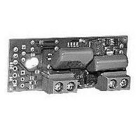
DMS-30 AC-Power Appl. Board
Manufacturer
Murata Power Solutions Inc
Datasheet
1.DMS-EB-ACDC-C.pdf
(4 pages)
Specifications of DMS-EB-AC/DC-C
Lead Free Status / RoHS Status
Lead free / RoHS Compliant


Functional Specifications
(T
Introduction
ered DMS-30PC or DMS-30LCD 3½ digit meters using the meter’s inter-
nal reference (SG13 is closed). This configuration is the most common
and works well for most simple voltage measurements. Please read all
of the following technical notes and perform any required modifications
before soldering the DMS-EB-AC/DC onto the host meter.
(3½ digit resolution) and DMS-40 (4½ digit resolution) meters. However,
Application 5, installing the span (R4) and offset (R5) adjust potenti-
ometers, can only be used with DMS-30PC/LCD meters. Also note that
some of the other applications require the installation of R4 and R5. See
Technical Note 4 when using the DMS-EB-AC/DC with DMS-40LCD
meters.
terminals 1 and 2 before making modifications or installing
user-supplied components on the DMS-EB-AC/DC board! In many
applications, the DMS-EB-AC/DC installation is subject to electrical-code
requirements (for example, the NEC in the USA). Fusing, grounding,
wire gauges, and leakage currents may be regulated items. Since the
DMS-EB-AC/DC is a line-operated device, it presents a shock hazard
and should be installed only by qualified personnel. Do not hesitate to
contact DATEL if you have any questions.
TECHNICAL NOTES
1. Soldering and Wiring: DATEL recommends the use of “no-clean”
DMS-EB-AC/DC-C
Ordering Information
A
AC Supply Voltage:
AC Supply Current @ 264Vac/60Hz
Isolation
Operating Temperature Range
Storage Temperature Range
Humidity
Dimensions
TB1 and TB2 Wire Size and Strip Length
Wire Size
Strip Length
Screw Torque
Rated Voltage
solders when installing components or making modifications to the
DMSEB-AC/DC. Before mating the DMS-EB-AC/DC to the host meter,
ensure that modifications, if any, have been correctly made and that
all cut solder-gaps are fully open. Align pin 1 of the meter with pin 1 of
the DMS-EB-AC/DC, slide the board down flush to the meter’s housing
and solder all 12 pins. Lastly, carefully cut the meter’s 12 pins as close
as possible to the pc-board surface.
= +25°C)
As shipped, the DMS-EB-AC/DC is configured for use with +5V-pow-
Many of the applications described below apply to both DMS-30
!IMPORTANT! AC power must be disconnected from TB2
AC power supply board
100 to 264Vac @ 47-68Hz
60mA, maximum
1500Vac, minimum
0 to +60°C
–25 to +75°C
0 to 95%, non-condensing
2.02" (51.31mm)L x 0.82" (20.8mm)W
x 0.60" (15.3mm)D
16 to 22 AWG (solid or stranded)
0.25" (6.35mm)
3.6 pound-inches (0.4Nm)
310Vac
www.murata-ps.com
Accessory Board for DMS-30PC/LCD Panel Meters
2. Grounding/Isolation: Because DMS-30 and DMS-40 meters are
3. Input Resistor Dividers (See Figure 4): Use 1%, or better, metal film
4. DMS-40LCD Meters: To change the input range on DMS-40LCD
5. Calibration Potentiometer Adjustment Holes: Two overlapping
6. Solder Gap Identification (See Figure 2): Each solder gap’s respec-
7. AC Supply Transients: The DMS-EB-AC/DC can withstand transients
8. AC Supply Fusing: The DMS-EB-AC/DC board does not have an
Making absolutely sure that the AC supply is de-energized (OFF), con-
nect the AC supply to TB2 terminals 1 (AC LO) and 2 (AC HI). Connect
the input signal being measured to TB1 terminals 1 (+HI) and 2 (-LO).
housed in a plastic case, a connection to AC earth ground is not
required. When wired per the instructions above, the DMS-EB-AC/DC
board provides a minimum of 1500V isolation between its AC supply
input (TB2) and its input signal (TB1). However, please keep in mind
that in many applications the LO side of the input signal may be con-
nected to AC ground (i.e., earth ground) elsewhere in the system. Any
Issues pertaining to grounding and/or isolation of the DMS-EB-
AC/DC power supply board must be referred to qualified technical
personnel.
resistors for R1 and R2 in DMS-30 applications, and 0.5%, or better, in
DMS-40LCD applications. Make sure the resistor’s power and voltage
ratings are adequate for the given application. Using tight-tolerance
resistors in input scaling circuits allows most calibration adjustments
to be made with the meter’s internal rear-mounted potentiometers,
through the access holes provided (see Technical Note 5 below).
meters from the default low-range (i.e., with pin 2 of the meter open)
to the high range, short pin 2 to pin 1 (+5V) on the top right side of
DMS-EB-AC/DC board (refer to Figure 2 and the DMS-40LCD data
sheet for more information).
holes on the DMS-EB-AC/DC provide access to the built-in ¾-turn
calibration potentiometer on DMS-30 meters or the 3-turn potentiom-
eter on DMS-40LCD meters. The adjustment range of both pots is very
narrow. See the applicable product data sheet for more information on
each meter’s calibration potentiometers.
tive number is printed directly on the pc-board surface in copper etch.
Be sure to double check all solder gap modifications before applying
ac power and the input signal to the DMS-EB-AC/DC.
typically found in instrumentation environments. Installations which
contain ac-powered equipment capable of generating large voltage
and/or current surges should use external energy-clamping devices. A
1500 Watt bi-directional transzorb with a minimum stand-off voltage
rating that matches the highest line-voltage peaks will provide ad-
ditional protection under severe fault conditions. If a transzorb or other
energy limiting device is used, the ac supply feeding the DMS-EB-AC/
DC should have its own fuse. Refer to the fusing section for more
information.
internal fusing device. If required, a 0.2A slow-acting fuse is recom-
mended. Be sure the fuse is rated for the applied line voltage.
Technical enquiries email: sales@murata-ps.com, tel:
DMS-EB-AC/DC
100-264Vac Power Supply
MPM_DMS-EB-AC/DC.B01 Page 2 of 4
+1 508 339 3000
Related parts for DMS-EB-AC/DC-C
Image
Part Number
Description
Manufacturer
Datasheet
Request
R


Part Number:
Description:
DMS-30 Temp. Appl. Board Cel
Manufacturer:
Murata Power Solutions Inc
Datasheet:
Part Number:
Description:
DMS-30 Temp. Appl. Board Farn
Manufacturer:
Murata Power Solutions Inc
Datasheet:

Part Number:
Description:
Ac-to-rms Converter Application Board For Dms-30pc/lcd Meters
Manufacturer:
Murata Manufacturing Co., Ltd
Datasheet:
Part Number:
Description:
4-20ma Current Loop Application Board For Dms-30lcd Meters
Manufacturer:
Murata Manufacturing Co., Ltd
Datasheet:
Part Number:
Description:
High-accuracy Temperature Sensor Boards Dms-30pc/lcd-0 Meters
Manufacturer:
Murata Manufacturing Co., Ltd
Datasheet:
Part Number:
Description:
Dc/dc Converter And Isolation Board For Dms-30pc/lcd Meters
Manufacturer:
Murata Manufacturing Co., Ltd
Datasheet:
Part Number:
Description:
100-264vac Power Supply Accessory Board For Dms-30pc/lcd Panel Meters
Manufacturer:
Murata Manufacturing Co., Ltd
Datasheet:

Part Number:
Description:
Application Board
Manufacturer:
Murata Power Solutions Inc
Datasheet:

Part Number:
Description:
DC/DC CONVERTER FOR DMS30PC METERS
Manufacturer:
Murata Power Solutions Inc
Datasheet:

Part Number:
Description:
DATEL PANEL METERS
Manufacturer:
Murata Power Solutions Inc
Datasheet:

Part Number:
Description:
DMS-EB Blank PC-Board DMS-30
Manufacturer:
Murata Power Solutions Inc
Datasheet:

Part Number:
Description:
POWER OVER ETHERNET MODULE
Manufacturer:
Murata Power Solutions Inc
Datasheet:

Part Number:
Description:
POWER OVER ETHERNET MODULE
Manufacturer:
Murata Power Solutions Inc
Datasheet:

Part Number:
Description:
POWER OVER ETHERNET MODULE
Manufacturer:
Murata Power Solutions Inc
Datasheet: