DMS-EB-AC/DC-C Murata Power Solutions Inc, DMS-EB-AC/DC-C Datasheet - Page 4
DMS-EB-AC/DC-C
Manufacturer Part Number
DMS-EB-AC/DC-C
Description
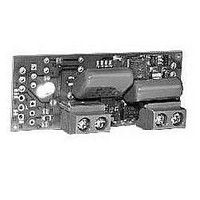
DMS-30 AC-Power Appl. Board
Manufacturer
Murata Power Solutions Inc
Datasheet
1.DMS-EB-ACDC-C.pdf
(4 pages)
Specifications of DMS-EB-AC/DC-C
Lead Free Status / RoHS Status
Lead free / RoHS Compliant


Example
4. DC Current Measurements (Use +/-200mV Range DMS-30-0
Murata Power Solutions, Inc.
11 Cabot Boulevard, Mansfield, MA 02048-1151 U.S.A.
Tel: (508) 339-3000 (800) 233-2765 Fax: (508) 339-6356
www.murata-ps.com email: sales@murata-ps.com ISO 9001 and 14001 REGISTERED
Murata Power Solutions, Inc. makes no representation that the use of its products in the circuits described herein, or the use of other
technical information contained herein, will not infringe upon existing or future patent rights. The descriptions contained herein do not imply
the granting of licenses to make, use, or sell equipment constructed in accordance therewith. Specifications are subject to change without
notice.
Using a DMS-30-1 meter (+/-2V range), Vin is 0-5Vdc and the display
reading must be “000” to “1500”
Meters):
When using R2 location for a dc current-shunt, please note that the
pc-board copper traces which short out R1 can only carry currents
up to 0.2A (200mA). However, dc currents up to 2A can be accommo-
dated if a 20AWG jumper wire is soldered in location R1. Be sure R2
has a sufficient power rating to safely carry the full load current. Refer
to DMS Application Note 6 for more information on dc ammeters.
SG4
1. Assume R1 = 1.0MΩ.
2. R2 = (FSI x R1) / ( |Vin| - FSI)
3. Calibrate the meter using a known voltage source. Adjust R4 to
R2 = (1.500 x 1,000,000) / (5.0 - 1.500)
R2 = 428,571Ω or 432kΩ
compensate for tolerances in R1 and R2.
SG13
DP4
SG7
SG8
12
SG12
Figure 3. R4 and R5 Installation
R5
R4
SG10
R3
SG14
SG11
SG6
SG9
TB1
HI(+)
1
LO(–)
www.murata-ps.com
2
© 2008 Murata Power Solutions, Inc.
12/30/08
APPLICATIONS
USA:
Canada:
UK:
France:
Germany:
Japan:
China:
Singapore:
Accessory Board for DMS-30PC/LCD Panel Meters
Example
SG4
1. Install R2: R2 = FSR / (I
2. Configure the DMS-EB for span adjust using the procedure previ-
3. Apply the input signal (current) to TB1 (+) HI and (–) LO.
4. Adjust R4 for desired full scale readings.
5. Enable the appropriate decimal point using SG1, SG2, or SG3.
Using a DMS-30-0 meter, a 0.100 Ampere input must read “100.0”
meter reading (0 up to 1999, disregarding any decimal points), and
I
ously outlined for the DMS-30-0 (+/-200mV range).
mA on the display.
R2 = 1000 / (0.1 x 10000)
R2 = 1 Ohm
Enable DP3 via SG3 for a display reading of “100.0.”
MAX
SG13
Mansfield (MA), Tel: (508) 339-3000, email: sales@murata-ps.com
Toronto, Tel: (866) 740-1232, email: toronto@murata-ps.com
Milton Keynes, Tel: +44 (0)1908 615232, email: mk@murata-ps.com
Montigny Le Bretonneux, Tel: +33 (0)1 34 60 01 01, email: france@murata-ps.com
München, Tel: +49 (0)89-544334-0, email: munich@murata-ps.com
Tokyo, Tel: 3-3779-1031, email: sales_tokyo@murata-ps.com
Osaka, Tel: 6-6354-2025, email: sales_osaka@murata-ps.com
Shanghai, Tel: +86 215 027 3678, email: shanghai@murata-ps.com
Guangzhou, Tel: +86 208 221 8066, email: guangzhou@murata-ps.com
Parkway Centre, Tel: +65 6348 9096, email: singapore@murata-ps.com
DP4
SG7
SG8
is current in Amperes.
12
Technical enquiries email: sales@murata-ps.com, tel:
SG12
Figure 4. R1 and R2 Installation
SG14
MAX
DMS-EB-AC/DC
. x 10000) where FSR is the desired
R3
SG11
100-264Vac Power Supply
SG6
SG9
R1
R2
MPM_DMS-EB-AC/DC.B01 Page 4 of 4
TB1
HI(+)
1
LO(–)
2
+1 508 339 3000
Related parts for DMS-EB-AC/DC-C
Image
Part Number
Description
Manufacturer
Datasheet
Request
R


Part Number:
Description:
DMS-30 Temp. Appl. Board Cel
Manufacturer:
Murata Power Solutions Inc
Datasheet:
Part Number:
Description:
DMS-30 Temp. Appl. Board Farn
Manufacturer:
Murata Power Solutions Inc
Datasheet:

Part Number:
Description:
Ac-to-rms Converter Application Board For Dms-30pc/lcd Meters
Manufacturer:
Murata Manufacturing Co., Ltd
Datasheet:
Part Number:
Description:
4-20ma Current Loop Application Board For Dms-30lcd Meters
Manufacturer:
Murata Manufacturing Co., Ltd
Datasheet:
Part Number:
Description:
High-accuracy Temperature Sensor Boards Dms-30pc/lcd-0 Meters
Manufacturer:
Murata Manufacturing Co., Ltd
Datasheet:
Part Number:
Description:
Dc/dc Converter And Isolation Board For Dms-30pc/lcd Meters
Manufacturer:
Murata Manufacturing Co., Ltd
Datasheet:
Part Number:
Description:
100-264vac Power Supply Accessory Board For Dms-30pc/lcd Panel Meters
Manufacturer:
Murata Manufacturing Co., Ltd
Datasheet:

Part Number:
Description:
Application Board
Manufacturer:
Murata Power Solutions Inc
Datasheet:

Part Number:
Description:
DC/DC CONVERTER FOR DMS30PC METERS
Manufacturer:
Murata Power Solutions Inc
Datasheet:

Part Number:
Description:
DATEL PANEL METERS
Manufacturer:
Murata Power Solutions Inc
Datasheet:

Part Number:
Description:
DMS-EB Blank PC-Board DMS-30
Manufacturer:
Murata Power Solutions Inc
Datasheet:

Part Number:
Description:
POWER OVER ETHERNET MODULE
Manufacturer:
Murata Power Solutions Inc
Datasheet:

Part Number:
Description:
POWER OVER ETHERNET MODULE
Manufacturer:
Murata Power Solutions Inc
Datasheet:

Part Number:
Description:
POWER OVER ETHERNET MODULE
Manufacturer:
Murata Power Solutions Inc
Datasheet: