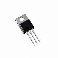
IRF730APBF Vishay, IRF730APBF Datasheet - Page 8

IRF730APBF
Manufacturer Part Number
IRF730APBF
Description
N CHANNEL MOSFET, 400V, 5.5A TO-220
Manufacturer
Vishay
Specifications of IRF730APBF
Transistor Polarity
N Channel
Continuous Drain Current Id
5.5A
Drain Source Voltage Vds
400V
On Resistance Rds(on)
1ohm
Rds(on) Test Voltage Vgs
10V
Threshold Voltage Vgs Typ
4.5V
Fet Type
MOSFET N-Channel, Metal Oxide
Fet Feature
Standard
Rds On (max) @ Id, Vgs
1 Ohm @ 3.3A, 10V
Drain To Source Voltage (vdss)
400V
Current - Continuous Drain (id) @ 25° C
5.5A
Vgs(th) (max) @ Id
4.5V @ 250µA
Gate Charge (qg) @ Vgs
22nC @ 10V
Input Capacitance (ciss) @ Vds
600pF @ 25V
Power - Max
74W
Mounting Type
Through Hole
Package / Case
TO-220-3 (Straight Leads)
Gate Charge Qg
22 nC
Minimum Operating Temperature
- 55 C
Configuration
Single
Resistance Drain-source Rds (on)
1 Ohm @ 10 V
Forward Transconductance Gfs (max / Min)
3.1 S
Drain-source Breakdown Voltage
400 V
Gate-source Breakdown Voltage
+/- 30 V
Continuous Drain Current
5.5 A
Power Dissipation
74000 mW
Maximum Operating Temperature
+ 150 C
Mounting Style
Through Hole
Lead Free Status / RoHS Status
Lead free / RoHS Compliant
Lead Free Status / RoHS Status
Lead free / RoHS Compliant, Lead free / RoHS Compliant
Other names
*IRF730APBF
Available stocks
Company
Part Number
Manufacturer
Quantity
Price
Company:
Part Number:
IRF730APBF
Manufacturer:
VISHAY
Quantity:
20 000
Part Number:
IRF730APBF
Manufacturer:
VISHAY/威世
Quantity:
20 000
Document Number: 91045
IR WORLD HEADQUARTERS: 233 Kansas St., El Segundo, California 90245, USA Tel: (310) 252-7105
‚
ƒ
Notes:
Repetitive rating; pulse width limited by
I
R
max. junction temperature. ( See fig. 11 )
T
Starting T
SD
J
G
≤ 150°C
= 25Ω, I
≤ 5.5A, di/dt ≤ 90A/µs, V
NOTES:
1 DIMENSIONING & TOLERANCING PER ANSI Y14.5M, 1982.
2 CONTROLLING DIMENSION : INCH
14.09 (.555)
13.47 (.530)
15.24 (.600)
14.84 (.584)
E X A M P L E :
2.87 (.113)
2.62 (.103)
J
3X
2.54 (.100)
= 25°C, L = 19mH
AS
1.40 (.055)
1.15 (.045)
= 5.5A. (See Figure 12)
2X
T H I S I S A N I R F 1 0 1 0
L O T C O D E 1 7 8 9
A S S E M B L E D O N W W 1 9 , 1 9 9 7
I N T H E A S S E M B L Y L I N E " C "
N o t e :
p o s i t i o n in d ic a t e s " L e a d - F r e e "
10.54 (.415)
10.29 (.405)
" P " i n a s s e m b l y li n e
1
DD
2
≤ V
3
4
(BR)DSS
3X
0.36 (.014)
6.47 (.255)
6.10 (.240)
0.93 (.037)
0.69 (.027)
1.15 (.045)
4.06 (.160)
3.55 (.140)
,
MIN
3.78 (.149)
3.54 (.139)
M
„
…
- A -
B
Pulse width ≤ 300µs; duty cycle ≤ 2%.
C
as C
Data and specifications subject to change without notice.
oss
A
M
eff. is a fixed capacitance that gives the same charging time
oss
I N T E R N A T I O N A L
3 OUTLINE CONFORMS TO JEDEC OUTLINE TO-220AB.
4 HEATSINK & LEAD MEASUREMENTS DO NOT INCLUDE BURRS.
R E C T I F I E R
while V
A S S E M B L Y
L O T C O D E
L O G O
4.69 (.185)
4.20 (.165)
DS
is rising from 0 to 80% V
- B -
1.32 (.052)
1.22 (.048)
2.92 (.115)
2.64 (.104)
3X
H E X F E T
1 - G A T E
2 - D R A I N
3 - S O U R C E
4 - D R A I N
0.55 (.022)
0.46 (.018)
TAC Fax: (310) 252-7903
LEAD ASSIGNMENTS
L E A D A S S I G N M E N T S
1 - GATE
2 - DRAIN
3 - SOURCE
4 - DRAIN
DSS
D A T E C O D E
Y E A R 7 =
W E E K 1 9
L I N E C
P A R T N U M B E R
I G B T s , C o P A C K
1 - G A T E
2 - C O L L E C T O R
3 - E M I T T E R
4 - C O L L E C T O R
www.vishay.com
1 9 9 7
02/04
8


