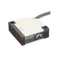
E3JK-DS30M1-US Omron, E3JK-DS30M1-US Datasheet - Page 12

E3JK-DS30M1-US
Manufacturer Part Number
E3JK-DS30M1-US
Description
UL CSA MARK DIFFUSE L-ON
Manufacturer
Omron
Series
E3JKr
Specifications of E3JK-DS30M1-US
Rohs Compliant
YES
Sensing Distance
11.811" (300mm)
Sensing Method
Reflective, Diffuse
Sensing Object
White Paper
Output Configuration
Relay - Light-ON
Sensing Light
Infrared
Mounting Type
Bracket Mount, Vertical
Current - Supply
-
Voltage - Supply
24 V ~ 240 V
Package / Case
Module, Pre-Wired
Features
Universal AC/DC Supply Voltage
Lead Free Status / RoHS Status
Lead free / RoHS Compliant
Lead Free Status / RoHS Status
Lead free / RoHS Compliant
Dimensions
Sensors
E3JM-10@4(T)-N *1
E3JK-5@@-N *2
*1. Models numbers for Through-beam Sensors (E3JM-10@4(T)-N) are for sets that include both the Emitter and Receiver.
*2. Models numbers for Through-beam Sensors (E3JK-5@@-N) are for sets that include both the Emitter and Receiver.
Accessories (Order separately)
Seal-type Long Slit (For E3JM/E3JK)
E39-S39
Materials: Polyester
0.1-mm thick
Emitter: E3JM-10L-N
Receiver: E3JM-10D@4(T)-N
Emitter: E3JK-5L-N
Receiver: E3JK-5D@@-N
The model number of the Emitter is E3JM-10L-N for all models. The model number of the Receiver, by adding "D" (example: E3JM-10DM4-N). Refer to Ordering
Information to confirm model numbers for Emitter and Receivers.
The model number of the Emitter is E3JK-5L-N 2M for all models. The model number of the Receiver, by adding "D" (example: E3JK-5DM1-N 2M). Refer to Ordering
Information to confirm model numbers for Emitter and Receivers.
80
65
15
Mounting Holes
Mounting Holes
44
Two, M6
(A) *2
Two, M6
42
42
25
50
4.1
Lens: 14.8 dia.
28
(A) *1
Optical axis
22
Note: The operating mode switch and timer
13.4
6.4
18
1.6
40
*1. Mounting Brackets can be used on the A side
*2. Emitter: Power indicator
*3. The Emitter has two conductors.
Two, M4×30
*1. Emitter: Power indicator
*2. Mounting Brackets can be used on the A side.
24.5
(M4 × 20 screws: 2 sets provided)
Steel
Receiver: Light indicator
With Mounting Bracket Attached
9
mode switch are located inside the cover.
Lens: 14.8 dia.
Indicator *2
22
Receiver: Light indicator (without timer function)
Operation indicator (with timer function)
With Mounting Bracket Attached
21.5
3
14
6
12
20
12.4
Steel
Optical axis
1±
36.5
0.1
6.4
20 26.5
5
11.5
10°
8
4
6-dia. vinyl-insulated round
cable with 5 conductors
(Conductor cross section: 0.3 mm
Insulator diameter: 1.5 mm),
Standard length: 2 m *3
6 dia.
54.5
40
39.5
Indicator *1
65
9
75
18
6 dia.
R56.6
50
40
58
42
Hexagonal nut
(Diagonal: 22)
Applicable cable:
6 to 8 dia.
18
6
6
JIS
B 0202
PF1/2
(12.4)
6.4
7
40
5
12
21
60
2
,
Mounting Brackets
Refer to E39-L/F39-L/E39-S/E39-R for details.
E3JM-R4@4(T)
E3JM-DS70@4(T)
E3JK-R2@@
E3JK-R4@@
E3JK-DS30@@
80
Tolerance class IT16 applies to dimensions in this datasheet unless otherwise specified.
Mounting Holes
Mounting Holes
65
15
47.5
Two, M6
Two, M6
(A) *2
42
42
50
Note: The operating mode switch, timer mode switch, and
25
(A) *1
28
4.1
sensitivity adjuster (sensitivity adjuster: E3JM-
DS70@4(T) only) are located inside the cover.
*1. Light indicator (without timer function)
*2. Mounting Brackets can be used on the A side.
13.4
Emitter
Receiver
18
22
Operation indicator (with timer function)
40
*1. Mounting Brackets can be used on the A side
*2. Sensitivity adjusters are not available on
Lens
(M4 × 20 screws: 2 sets provided)
Retro-reflective models.
6.4
Light indicator
Steel
Emitter
22
1.6
Two, M4 × 30
With Mounting Bracket Attached
25
12
24.5
With Mounting Bracket Attached
9
40
3
Steel
6
20
12.4
Sensitivity adjuster *2
6.4
Optical
axis
10°
4
5
6-dia. vinyl-insulated round
cable with 5 conductors
(Conductor cross section: 0.3 mm
Insulator diameter: 1.5 mm),
Standard length: 2 m
11.5
8
9
6 dia.
E3JM/E3JK
54.5
40
6 dia.
39.5
R56.6
Indicator *1
50
40
58
42
65
75
18
18
Hexagonal nut
(Diagonal: 22)
Applicable cable:
6 to 8 dia.
6
6.4
(Unit: mm)
7
6
40
5
12
JIS
B 0202
PF1/2
(12.4)
21
60
2
,
12


