E3JK-DS30M1-US Omron, E3JK-DS30M1-US Datasheet - Page 9
E3JK-DS30M1-US
Manufacturer Part Number
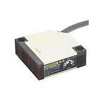
E3JK-DS30M1-US
Description
UL CSA MARK DIFFUSE L-ON
Manufacturer
Omron
Series
E3JKr
Specifications of E3JK-DS30M1-US
Rohs Compliant
YES
Sensing Distance
11.811" (300mm)
Sensing Method
Reflective, Diffuse
Sensing Object
White Paper
Output Configuration
Relay - Light-ON
Sensing Light
Infrared
Mounting Type
Bracket Mount, Vertical
Current - Supply
-
Voltage - Supply
24 V ~ 240 V
Package / Case
Module, Pre-Wired
Features
Universal AC/DC Supply Voltage
Lead Free Status / RoHS Status
Lead free / RoHS Compliant
Lead Free Status / RoHS Status
Lead free / RoHS Compliant


I/O Circuit Diagrams
E3JM
Relay Output Models
DC SSR Output Models
Note: Connect terminal 1 to any polarity and terminal 2 to the power supply because there is no polarity on the Emitter side.
* Models numbers for Through-beam Sensors (E3JM-10@4(T)-N) are for sets that include both the Emitter and Receiver.
E3JK
Relay Output Models
DC SSR Output Models
Note: Connect the brown cable to any polarity and the blue cable to the power supply because there is no polarity on the Emitter side.
* Models numbers for Through-beam Sensors (E3JK-5@@-N 2M) are for sets that include both the Emitter and Receiver.
E3JM-10M4(T)-N
E3JM-R4M4(T)
E3JM-DS70M4(T)
E3JM-10S4(T)-N
E3JM-R4S4(T)
E3JM-DS70S4(T)
E3JK-5M1-N
E3JK-5M2-N
E3JK-R2M1
E3JK-R2M2
E3JK-R4M1
E3JK-R4M2
E3JK-DS30M1
E3JK-DS30M2
E3JK-5S3-N
E3JK-R2S3
E3JK-R4S3
E3JK-DS30S3
The model number of the Emitter is E3JM-10L-N for all models. The model number of the Receiver, by adding "D" (example: E3JM-10DM4-N). Refer to Ordering
Information to confirm model numbers for Emitter and Receivers.
The model number of the Emitter is E3JK-5L-N 2M for all models. The model number of the Receiver, by adding "D" (example: E3JK-5DM1-N 2M). Refer to Ordering
Information to confirm model numbers for Emitter and Receivers.
Model
Model
Model
Model
*
*
*
*
*
L-ON (Ta)
(E3JK-@@M1)
D-ON (Ta)
(E3JK-@@M2)
Light indicator
(red)
Light indicator
(red)
Light indicator
(red)
Light indicator
(red)
L-ON output
D-ON output
D-ON (Ta)
L-ON (Ta)
D-ON (Ta)
L-ON (Ta)
No incident light
No incident light
No incident light
No incident light
Incident light
Incident light
Incident light
Incident light
Timing chart
Timing chart
Timing chart
Timing chart
OFF
OFF
OFF
OFF
OFF
OFF
OFF
OFF
OFF
ON
ON
ON
OFF
OFF
OFF
ON
ON
ON
ON
ON
ON
ON
ON
ON
Photo-
electric
Sensor
main
circuit
Note: The output stage leakage currents are 0.1 mA max., respectively.
Photo-
electric
Sensor
main
circuit
Photoelectric
Sensor main
circuit
Photoelectric
Sensor main
circuit
Circuit
Circuit
Drive
Drive
Circuit
Circuit
Drive
Drive
Output circuit
Output circuit
Output circuit
Output circuit
Tb
Tc
Ta
1
2
3
4
5
Brown
Blue
White
Black
Gray
D/ON
L/ON
(Built-in Relay: G6C)
Tb
Tc
Ta
(Built-in Relay: G6C)
D/ON
24 to 240 VAC
12 to 240 VDC
L/ON
No polarity
24 to 240 VAC
12 to 240 VDC
Brown
Source
Power
No polarity
Blue
Gray
Black
White
Contact output
Power
source
1
2
3
5
4
Contact output
24 to 240 VAC
12 to 240 VDC
24 to 240 VAC
12 to 240 VDC
No polarity
E3JM/E3JK
NO
NC
COM
Source
I
Power
No polarity
I
I
1+
1
2
Source
I
Power
Load
Load
2<
I
I
1
2
100 mA
I
1+
I
Load
Load
2<
100 mA
max.
48 VDC
48 VDC
max.
9
Related parts for E3JK-DS30M1-US
Image
Part Number
Description
Manufacturer
Datasheet
Request
R

Part Number:
Description:
G6S-2GLow Signal Relay
Manufacturer:
Omron Corporation
Datasheet:
Part Number:
Description:
Compact, Low-cost, SSR Switching 5 to 20 A
Manufacturer:
Omron Corporation
Datasheet:
Part Number:
Description:
Manufacturer:
Omron Corporation
Datasheet:
Part Number:
Description:
Manufacturer:
Omron Corporation
Datasheet:
Part Number:
Description:
Manufacturer:
Omron Corporation
Datasheet:
Part Number:
Description:
Manufacturer:
Omron Corporation
Datasheet:
Part Number:
Description:
Manufacturer:
Omron Corporation
Datasheet:
Part Number:
Description:
Manufacturer:
Omron Corporation
Datasheet: