B5-1 IDEC, B5-1 Datasheet
B5-1
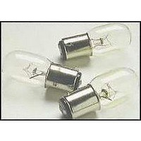
Manufacturer Part Number
B5-1
Description
LAMP, INCANDESCENT, 120V, 7W
Manufacturer
IDEC
Specifications of B5-1
Supply Voltage
120VAC
Base Type
Bayonet
Bulb Size
T-20
Power Rating
7W
Average Bulb Life
2000h
Forward Voltage
120V
Peak Reflow Compatible (260 C)
No
Leaded Process Compatible
No
Lead Free Status / RoHS Status
Contains lead / RoHS non-compliant
OUTPUT LED (S60…B01/B51/C01/C11/F01/T51)
The yellow LED ON indicates that the N.O. (normally open) output
status is closed.
STABILITY LED (S60…B01/B51/C01/C11/F01)
The green LED ON indicates that the received signal has a reserve
greater than 30% compared to the output switching value.
POWER ON LED (S60…G00)
The green LED indicates that the sensor is operating.
TRIMMER (S60…B01/B51/C01/C11/F01/T51)
The trimmer can be used to adjust sensitivity; the operating distance
increases turning the trimmer clockwise.
WARNING: The trimmer rotation is limited to 270° by a mechanical stop.
Do not apply excessive torque when adjusting (max 40 Nmm).
The sensor can be positioned by
means of the three housing’s holes
using two screws (M4x25 or longer, 1.5
Nm maximum tightening torque) with
washers.
Various orientable fixing brackets to
ease
available
accessories listed in the catalogue).
The operating distance is measured
from the front surface of the sensor
optics.
The M12 connector can be oriented at two different positions using the
specific fastening spring and rotating the block of 180°.
The connections are compliant to the EN 60947-5-2 standard.
M12 CONNECTOR
S60…B01/B51/C01/C11/F01/T51
BROWN
WHITE
BLACK
BLUE
the
INSTRUCTION MANUAL
(please
sensor
1
4
3
2
S60 SERIES
+
INSTALLATION
CONNECTIONS
positioning
refer
10 … 30 Vdc
N.C. OUTPUT
N.O. OUTPUT
0 V
CONTROLS
2
3
to
are
the
BROWN
WHITE
BLACK
BLUE
1
4
S60…G00
1
4
3
2
+
10 … 30 Vdc
TEST +
TEST -
0 V
Power supply:
Ripple:
Current consumption
(output current excluded):
Outputs:
Output current:
Output saturation voltage:
Response time:
Switching frequency:
Indicators:
Setting:
Operating temperature:
Storage temperature:
Electrical shock protection:
Operating distance (typical values):
Emission type:
Ambient light rejection:
Vibrations:
Shock resistance:
Housing material:
Lens material:
Mechanical protection:
Connections:
Weight:
OUTPUT LED
POWER ON LED (S60-G00)
STABILITY LED
TRIMMER
11 6
50
42
23.6
14
TECHNICAL DATA
RED (660 nm) mod.B01/B51/C01/T51; INFRARED (880 nm) mod.C11/G00
PMMA window, polycarbonate lens / glass window and lens mod. B51/T51
0.5 mm amplitude, 10 … 55 Hz frequency, for every axis (EN60068-2-6)
DIMENSIONS
1 kHz mod. B01/B51/T51; 500 Hz max. mod. C01/C11/F01
mm
STABILITY LED (GREEN) (mod. B01/B51/C01/C11/F01)
sensitivity trimmer (mod. B01/B51/C01/C11/F01/T51)
0.5 ms mod. B01/B51/T51; 1 ms mod. C01/C11/F01
11 ms (30 G) 6 shock for every axis (EN60068-2-27)
PNP or NPN; 30 Vcc max. (short-circuit protection)
90 g. max. cable vers. / 40 g. max. connector vers.
B51: 0…3m on R2 (0…2 m on R2 mirror rejection)
2 m cable ∅ 4 mm / M12-4 pole connector
S60...B01/C01/C11/F01/G00
POWER ON LED (GREEN) (mod.G00)
CABLE VERSION
according to EN 60947-5-2
10 … 30 Vdc (limit values)
OUTPUT LED (YELLOW)
T51: 0…1.5 m on R2
B01: 0.1…6 m on R2
F01/G00: 0…20 m
C11: 5…200 cm
100 mA max.
-25 … 55 °C
-25 … 70 °C
C01: 1…90 cm
35 mA max.
2 Vpp max.
Class 2
M12
Ø15
≤ 2 V
IP67
15
ABS
S60...B51/T51
M12
Ø15
15
Setting of S60…B01/B51/T51
Position the sensor and reflector aligned on opposite sides.
Turn the sensitivity trimmer to the maximum position.
Moving the sensor both vertically and horizontally, determine the power
on and off points of the yellow LED (OUT) and then mount the sensor in
the middle of the points defined.
Optimum operation is obtained when the green LED (mod.B01/B51) is
ON and the yellow LED is OFF.
B01/B51 models: If necessary reduce sensitivity in
order to detect very small targets. In order to improve
alignment, repeat the procedure detailed above whilst
progressively reducing the sensitivity.
T51 model: Turn the sensitivity trimmer counterclockwise until the yellow
LED turns ON (pos.A).
Turn slowly the trimmer again clockwise until the yellow LED turns OFF
(Operating condition, pos.B).
Setting of S60…F01/G00
Position the sensors aligned on opposite sides.
Turn the sensitivity trimmer to maximum: moving the sensor both
vertically and horizontally, determine the power on and off points of the
yellow LED (OUT) and then mount the sensor in the middle of the points
defined. Optimum operation is obtained when the green LED is ON and
the yellow LED is OFF.
If necessary, reduce sensitivity using the trimmer, in order to detect very
small targets. In order to improve alignment, repeat the procedure
detailed above whilst progressively reducing the sensitivity.
Setting of S60…C01/C11
Turn the sensitivity trimmer to minimum: the green LED
is ON, the yellow LED is OFF.
Position the target to detect in front of the sensor.
Turn the sensitivity trimmer clockwise until the yellow
LED turns ON (Target detected state, pos.A).
Remove the target, the yellow LED turns OFF.
Turn the sensitivity trimmer clockwise until the yellow LED turns ON
(Background detected state, pos.B).
The trimmer reaches maximum if the background is not detected.
Turn the trimmer to the intermediate position C, between the two
positions A and B. The green LED must be ON.
The TEST+ and TEST- inputs can be used to inhibit the emitter and
verify that the system is correctly operating.
The receiver output should switch when the test is activated while the
beam is uninterrupted.
The inputs activating voltage range is 10 … 30 Vdc, whilst respecting the
polarity.
The emission is switched off connecting TEST+ to Vdc and TEST- to
0V.
www.idec-ds.com
800-262-4332
-------------------------------------------------------------------------------------------------
DECLARATION OF CONFORMITY
IDEC and DATASENSOR jointly declare under their sole responsibility
that these products conform to the 2004/108/CE, 2006/95/CE Directives,
and successive amendments.
-------------------------------------------------------------------------------------------------
IDEC and DATASENSOR reserve the right to make modifications and
improvements without prior notification.
TEST FUNCTION (S60…G00)
826003350 Rev.00
SETTING
MIN
MIN
A
A
B
C
MAX
MAX
B
Related parts for B5-1
Image
Part Number
Description
Manufacturer
Datasheet
Request
R

Part Number:
Description:
LAMP, INCAND, BAYONET, 30V, 10W
Manufacturer:
IDEC
Datasheet:

Part Number:
Description:
Cable; Between IDEC MicroSmart (port 1 or 2) and HG2F/3F/4F; 5 ft.
Manufacturer:
IDEC Corporation
Datasheet:
Part Number:
Description:
Cable; Between IDEC Micro^3C/ONC/MicroSmart (port 2) PLCs and HG2F/3F/4F; 5 ft.
Manufacturer:
IDEC Corporation
Datasheet:
Part Number:
Description:
Angled Key for Idec HS6B Safety Switch
Manufacturer:
IDEC Corporation
Datasheet:
Part Number:
Description:
Accessory, L-Shaped Key for Idec HS5B and HS5E Safety Switch
Manufacturer:
IDEC Corporation
Datasheet:
Part Number:
Description:
Accessory, Straight Key for Idec HS5B and HS5E Safety Switch
Manufacturer:
IDEC Corporation
Datasheet:
Part Number:
Description:
Straight Key for Idec HS6B Safety Switch
Manufacturer:
IDEC Corporation
Datasheet:
Part Number:
Description:
LIGHT TOWER 3 TIER RED/AMBER/GREEN 24VAC/DC WALL MOUNT
Manufacturer:
IDEC Corporation
Datasheet:
Part Number:
Description:
Flat Lens, 24V AC/DC, 1m Cable Length, Alternate: Red Green Color, IP67
Manufacturer:
IDEC Corporation
Datasheet:
Part Number:
Description:
LIGHT TOWER 2 TIER RED/GREEN 24VAC/DC WALL MOUNT
Manufacturer:
IDEC Corporation
Datasheet:
Part Number:
Description:
INDICATOR INCANDESCENT LAMP, GREEN
Manufacturer:
IDEC
Datasheet:

Part Number:
Description:
LAMP, INDICATOR, INCAND, AMB
Manufacturer:
IDEC
Datasheet:
Part Number:
Description:
LAMP, INDICATOR, INCAND, GRN
Manufacturer:
IDEC
Datasheet:
Part Number:
Description:
LAMP, INDICATOR, INCAND, GRN
Manufacturer:
IDEC
Datasheet:
Part Number:
Description:
LAMP, INDICATOR, INCANDESCENT, RED
Manufacturer:
IDEC
Datasheet: