AEDR-8400-142 Avago Technologies US Inc., AEDR-8400-142 Datasheet
AEDR-8400-142
Specifications of AEDR-8400-142


Related parts for AEDR-8400-142


AEDR-8400-142 Summary of contents
Page 1
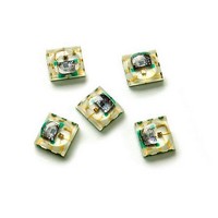
... Reflective Surface Mount Optical Encoder Data Sheet Description The AEDR-8400 encoder is the smallest optical encoder employing reflective technology for motion control purposes. The encoder houses an LED light source and a photo-detecting circuitry in a single package. The AEDR-8400 encoder offers two-channel quadrature digital outputs. Being TTL compatible, the outputs of the AEDR-8400 encoder can be interfaced directly with most of the signal processing circuitries ...
Page 2
... When used with a codewheel or linear codestrip, the encoder translates rotary or linear motion into digital outputs. As seen in the block diagram, the AEDR-8400 consists of three major components: a light emitting diode (LED) light source, a detector IC consisting photodiodes and lens to focus light beam from the emitter as well as light falling on the detector ...
Page 3
... Tangential Misalignment Angular Misalignment Codewheel/strip Tilt Codewheel/strip Gap Notes: 1. Refer to AEDR-8400 Reliability Datasheet 2. LED Current Limiting Resistor: Recommended series resistor = 121Ω (±1%) for 254 LPI and 255Ω (±1%) for 318 LPI. 3. Count frequency = velocity (rpm 60. 3 -40°C to 85°C -20° ...
Page 4
Encoding Characteristics Encoding characteristics over the recommended operating condition and mounting conditions. Parameter Pulse Width Error (Channel A) Pulse Width Error (Channel B) Phase Error Note: 1. Typical values represent the encoder performance at typical mounting alignment, whereas the maximum ...
Page 5
... A resistor to limit current to the LED is required. The recommended value is 121Ω (±1%) for 254 LPI and 255Ω (±1%) for 318 LPI. The resistor should be placed in series between the 2.8 V supply and pin 1 of the device (V result in an LED current of approximately 6mA. Moisture Sensitive Level The AEDR-8400 is specified to moisture sensitive level (MSL) 3. Outline Drawing Bottom View Encoder Pin Configuration ...
Page 6
... Encoder Orientation The AEDR-8400 is designed such that both the emitter and detector IC should be placed parallel to the win- dow/bar orientation, as shown. As such, the encoder is tolerant against radial play of ± 0.20mm. Direction of Movement With the emitter side of the encoder placed closer to the codewheel centre, Channel A leads Channel B when the codewheel rotates anti-clockwise and vice versa ...
Page 7
... Recommended Land Pattern for AEDR-8400 AEDR-8400 Pad Soldering In order to provide adequate mechanical strength for the AEDR-8400 encoder strongly recommended the all pin-outs need to be soldered including the encoder cen- ter pad. However, external circuit routing on PCB / FPC could actually route pin 2, pin 6 and center pad together hence to have a common ground for the encoder ...
Page 8
... Recommended Lead-free Reflow Soldering Temperature Profile Preheat Temperature 40 °C to 125 °C Temperature maintain above 217 °C Peak Temperature Time above 250 °C Note: Due to treatment of high temperature, AEDR-8400 compound may turn yellow after IR reflow. Ordering Information Option 0 AEDR-84 Number of Channels Packaging 0 – ...