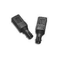
HFBR-1116TZ Avago Technologies US Inc., HFBR-1116TZ Datasheet

HFBR-1116TZ
Specifications of HFBR-1116TZ
Related parts for HFBR-1116TZ
HFBR-1116TZ Summary of contents
Page 1
... HFBR-2116TZ Receiver Fiber Optic Transmitter and Receiver Data Links for 155 MBd Data Sheet Description The HFBR-1116TZ/-2116TZ series of data links are high-performance, cost-efficient, transmitter and receiver modules for serial optical data communication applications specified at 155 MBd for ATM UNI applications. ...
Page 2
... MATERIAL PHOSPHOR BRONZE WITH 120 MICROINCHES TIN LEAD (90/10) OVER 50 MICROINCHES NICKEL. 3. UNITS = mm Figure 2. Package outline drawing. 2 PIN PHOTODIODE OPTICAL SIMPLEX ST SUBASSEMBLIES RECEPTACLE LED THREADS 3/8 – 32 UNEF-2A HFBR-111X/211XT DATE CODE (YYWW) SINGAPORE 12.19 MAX. 41 MAX. 5.05 0.9 2.45 19.72 17. 2.54 7.62 HOUSING PINS 0 ...
Page 3
OPTICAL PORT GND 10 NO PIN NO PIN GND GND CC GND 13 GND 4 DATA 14 3 GND DATA ...
Page 4
... When used in 115 Mbps SONET OC-3 applications, the perform- ance of Avago Technologies’ 1300 nm data link modules, HFBR- 1116TZ/-2116TZ, is guaranteed to the full conditions listed in the individual product specification tables. The data link modules may be used ...
Page 5
Shipping Container The data link modules are packaged in a shipping container designed to protect it from mechanical and ESD damage during shipment or storage GND Vdc ...
Page 6
Board Layout–Hole Pattern The Avago transmitter and receiver hole pattern is compatible with other data link modules from other vendors. The drawing shown in Figure 8 can be used as a guide in the mechanical layout of your circuit board. ...
Page 7
... HFBR-1116TZ TRANSMITTER TEST RESULTS OF , AND t ARE CORRELATED AND C r/f COMPLY WITH THE ALLOWED SPECTRAL WIDTH AS A FUNCTION OF CENTER WAVELENGTH FOR VARIOUS RISE AND FALL TIMES. Figure 9. HFBR-1116TZ transmitter output optical spectral width (FWHM) vs. transmitter output optical center wavelength and rise/fall times ...
Page 8
... HFBR-1116TZ Transmitter Pin-Out Table Pin Symbol Functional Description internal connect, used for mechanical strength only GND Ground 4 GND Ground 5 GND Ground 6 GND Ground 7 OMIT No pin internal connect, used for mechanical strength only internal connect, used for mechanical strength only 10 GND Ground ...
Page 9
... Data Input Voltage Differential Input Voltage Output Current Recommended Operating Conditions Parameter Ambient Operating Temperature Supply Voltage Data Input Voltage–Low Data Input Voltage–High Data and Signal Detect Output Load HFBR-1116TZ Transmitter Electrical Characteristics ( 4 5 Parameter Supply Current Power Dissipation Threshold Voltage Data Input Current– ...
Page 10
... HFBR-1116TZ Transmitter Optical Characteristics ( 4 5 Parameter Output Optical Power 62.5/125 0.275 Fiber Output Optical Power 50/125 0.20 Fiber Optical Extinction Ratio Output Optical Power at Logic “0” State Center Wavelength Spectral Width – FWHM – nm RMS Optical Rise Time Optical Fall Time ...
Page 11
... Signal Detect output shall be deasserted, logic-low (V ), within 350 s after a step OL decrease in the Input Optical Power. 23. The HFBR-1116TZ transmitter complies with the requirements for the tradeoffs between center wavelength, spectral width, and rise/fall times shown in Figure 9. This figure is derived from the FDDI PMD standard (ISO/IEC 9314-3: 1990 and ANSI X3 ...
Page 12
For product information and a complete list of distributors, please go to our website: Avago, Avago Technologies, and the A logo are trademarks of Avago Technologies Limited in the United States and other countries. Data subject to change. Copyright © ...


