200-525NR1 RF Solutions, 200-525NR1 Datasheet - Page 4
200-525NR1
Manufacturer Part Number
200-525NR1
Description
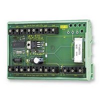
TRANSMITTER, DIN RAIL, 8I/P
Manufacturer
RF Solutions
Datasheet
1.210-525NR1.pdf
(11 pages)
Specifications of 200-525NR1
Svhc
No SVHC (15-Dec-2010)
External Length / Height
82mm
External Width
112mm
Frequency
434.525MHz
Operating Temperature Max
55°C
Operating Temperature Min
0°C
Range
1,000m


DS200-11 March ’06
1 Configuring a Remote Telemetry System
There are three Steps:
1. Pre-Configure the 200 or 201 series transmitter
2. Pre- Configure the 210Rx to operate with a 200 or 201 series transmitter
3. Marry a 200/201Tx to a 210Rx
1.1
1. Mapping the 200/201 Transmitter Inputs to the 210 Receiver Outputs
2. Enable Option Links (ENABLE 1-8)
3. Auto Transmit with Watchdog Mode ‘Auto Tx’
The Remote telemetry system automatically maps the 8 transmitter input channels to 8 receiver output
channels. The ‘8/15’ option link on the transmitter allows selection of channels 1-8 or 9-15 on the receiver.
The 200 and 201 Transmitters have eight ‘Enable’ Option links which must be fitted in order for the
corresponding input to be valid (otherwise the 210Tx will ignore it). This enables applications where many
transmitters are used with a single 210Rx (many to one relationship)
When the ‘Auto Tx’ link is made, the 200/201 Tx automatically transmits its data once within every 5
second period, in addition, channel 16 is allocated as a ‘system watchdog‘. As long as the 210Rx
continues to receive this signal then output ‘16’ is held ON. If for any reason (fault or RF interference) the
signal is not received for approx 20secs then output ‘16’ will drop out.
(200Tx/201Tx -> 210Rx)
200/201 Tx Option Link
Pre-Configure a 200/201 Transmitter Encoder
Modular Radio Telemetry System
Connected
Open
©2005 RF Solutions Ltd, www.rfsolutions.co.uk
Tel 01273 898000 Fax 01273 480661
210 Rx output Channels
9 – 15
1 – 8
Page 4
200 Series
Related parts for 200-525NR1
Image
Part Number
Description
Manufacturer
Datasheet
Request
R

Part Number:
Description:
200/400MMAC 16-bit DSP MICROCOMPUTER
Manufacturer:
Analog Devices Inc
Datasheet:

Part Number:
Description:
200 W LDMOS avionics power transistor for transmitter applications at frequencies from 1030 MHz to 1090 MHz
Manufacturer:
NXP Semiconductors
Datasheet:
Part Number:
Description:
200 W LDMOS power transistor for base station applications at frequencies from 1450 MHz to 1550 MHz
Manufacturer:
NXP Semiconductors
Datasheet:

Part Number:
Description:
200 W LDMOS power transistor for base station applications at frequencies from 2110 MHz to 2170 MHz
Manufacturer:
NXP Semiconductors
Datasheet:
Part Number:
Description:
200 W LDMOS power transistor for base station applications at frequencies from 2110 MHz to 2170 MHz
Manufacturer:
NXP Semiconductors
Datasheet:

Part Number:
Description:
IC ENCODER TRANSMITTER RF 8DIP
Manufacturer:
RF Solutions
Datasheet:

Part Number:
Description:
IC DECODER RECEIVER RF 18DIP
Manufacturer:
RF Solutions
Datasheet:

Part Number:
Description:
IC ENCODER 3 DGTL I/O SOT23-6
Manufacturer:
RF Solutions
Datasheet:

Part Number:
Description:
IC ENCODER 3 DGTL I/O 8-PDIP
Manufacturer:
RF Solutions
Datasheet:

Part Number:
Description:
IC DECODER 3 DGTL I/O 8-PDIP
Manufacturer:
RF Solutions
Datasheet:

Part Number:
Description:
IC DECODER 3 DGTL I/O 8-SOIC
Manufacturer:
RF Solutions
Datasheet:

Part Number:
Description:
118 SERIES AM REMOTE CONTROL SYSTEMS.
Manufacturer:
RF Solutions Ltd.