M210 RHOPOINT, M210 Datasheet - Page 3
M210
Manufacturer Part Number
M210
Description
Resistance Meter
Manufacturer
RHOPOINT
Datasheet
1.M210.pdf
(4 pages)
Specifications of M210
Wire Connection
4-Wire
Test Current
5mA
External Height
15cm
External Width
80mm
External Depth
38mm
Weight
480g
Length/height, External
150mm
Operating Temperature Min
5°C
Operating Temperature Max
35°C
Available stocks
Company
Part Number
Manufacturer
Quantity
Price

Part Number:
M210-A1A
Manufacturer:
IODMR
Quantity:
20 000
Company:
Part Number:
M2100-20U6999L
Manufacturer:
TE
Quantity:
5 400
Company:
Part Number:
M2100-20U6999L-208/240VAC
Manufacturer:
TE
Quantity:
5 400
Company:
Part Number:
M21036G-12
Manufacturer:
NNDSPEE
Quantity:
87
Part Number:
M21036G-12
Manufacturer:
MINDSPEED
Quantity:
20 000
Company:
Part Number:
M21038/27-01 Q1553-1
Manufacturer:
a
Quantity:
2


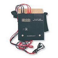
1. Plug either black plug into either black socket in the top of
the instrument and red plugs into red sockets.
2. Clip leads to circuit or component to be tested. Ensure that
both faces of clip make good electrical contact.
3. Press the ON button to read resistance.
Interpreting the display
1. The Milli-ohmeter will read directly in ohms or milli-ohms.
2. Fluctuating readings displayed. Check that the clips are
making good contact with the circuit under test, then look for
the cause of intermittency, e.g. dry solder joint, oxydised
or corroded terminals; slight mechanical movement of the
component(s) in the circuit under test should quickly reveal
the source of the problem.
3. Flashing “1” indicates that resistance in circuit exceeds
The ratio between the current and the voltage drop is calculated by the instrument using Ohm’s law (R=E/I) to display the result
in ohms.
Four clips would normally be required for connection but this could be tedious so a form of clip is used with the Milli-ohmeter.
The jaws are moulded in robust plastic and inset into each jaw face is a copper / silver inlay contact; these are insulated from
each other by the plastic mouldings. One contact face on each clip is connected to the current-generating circuit, the other face
is connected to the voltage-measuring circuit. In this way four wires are connected instantly by two clips. The resistance of the
connecting wires plays no part in the measuring so no “backing-off” is required as would be the case if a multi-meter were to be
used for the same measurment.
Using standard clip leads M210/9A
(Supplied as Standard)
Instructions for use
1. Insert plugs into their respective sockets as illustrated.
The outer plugs form the current circuit via the clips. The inner
plugs (with yellow bands) connect the probes in the voltage
measuring circuit.
2. Clip leads to circuit under tester.
3. Press ON button to read resistance when probes are in
contact with the circuit.
200 ohms.
4. “LO-BAT” displayed indicates low battery.
Battery Replacement
Slide down the cover at the rear, bottom of the instrument.
Fit new battery 9 volt pp3 (MN1604 or equivalent). Replace
cover.
Using probe and contact connectors
clip leads M210/9B
(Optional Extras)