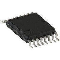
SI9118DB Vishay, SI9118DB Datasheet - Page 6

SI9118DB
Manufacturer Part Number
SI9118DB
Description
Pulse Width Modulation (PWM) Controller IC
Manufacturer
Vishay
Datasheet
1.SI9118DY-T1.pdf
(10 pages)
Specifications of SI9118DB
Silicon Manufacturer
Vishay
Application Sub Type
Pulse Width Modulation (PWM) Controller
Kit Application Type
Power Management
Silicon Core Number
SI9118
Kit Contents
Board
Lead Free Status / RoHS Status
Contains lead / RoHS non-compliant
Si9118/Si9119
Vishay Siliconix
PIN CONFIGURATIONS AND ORDERING INFORMATION
www.vishay.com
6
Pin Number
ORDERING INFORMATION
PIN DESCRIPTION
Part Number
Si9118DY
Si9118DY-T1
Si9118DY-T1-E3
Si9119DY
Si9119DY-T1
Si9119DY-T1-E3
10
11
12
13
14
15
16
PWM/PSM
1
2
3
4
5
6
7
8
9
COMP
SS/EN
C
V
+V
OSC
REF
FB
NI
IN
SYNC or V
PWM/PSM
Symbol
1
2
3
4
5
6
7
8
COMP
SS/EN
C
R
D
V
I
+V
-V
V
LIMIT
I
FB
D
REF
NI
OSC
OSC
MAX
CS
CC
IN
R
IN
Si9118DY
Top View
SC
SOIC
Input bus voltage ranging from 10 V to 200 V.
Connected to V
mode.
4 V reference voltage. Decouple with 0.1 µF ceramic capacitor.
Non-inverting input of an error amplifier.
Inverting input of an error amplifier.
Error amplifier output for external compensation network.
Programmable soft-start with external capacitor or externally controlled disable mode.
External capacitor to determine the switching frequency.
External resistor to determine the switching frequency.
Pulse by pulse peak current limiting pin. When the current sense voltage exceeds the current limit threshold,
the gate drive signal is terminated. I
Current sense input to control feedback response.
Si9118: slope compensation pin. Si9119: clock synchronization pin. Logic high to low transition from external
signal synchronizes the internal clock frequency.
Sets the maximum duty cycle. Internally, the maximum duty cycle is clamped to 80 %.
Single point ground.
Gate drive for the external MOSFET switch.
Supply voltage for the IC after the startup transition.
16
15
14
13
12
11
10
9
V
DR
-V
D
V
I
I
R
CS
LIMIT
REF
CC
SC
MAX
OSC
IN
forces the converter into PWM mode. Connected to -V
Temperature Range
- 40 to 85 °C
LIMIT
is also used to sense the current in pulse skipping mode.
PWM/PSM
Description
COMP
SS/EN
C
V
+V
OSC
REF
FB
NI
IN
1
2
3
4
5
6
7
8
Si9119DY
Top View
SOIC
IN
forces the converter into PSM
Package
SOIC-16
S-60550–Rev. D, 3-Apr-06
16
15
14
13
12
11
10
Document Number: 70815
9
V
DR
-V
D
SYNC
I
I
R
CS
LIMIT
CC
MAX
OSC
IN


