DK-START-4CGX15N/P Altera, DK-START-4CGX15N/P Datasheet
DK-START-4CGX15N/P
Specifications of DK-START-4CGX15N/P


Related parts for DK-START-4CGX15N/P


DK-START-4CGX15N/P Summary of contents
Page 1
... Innovation Drive San Jose, CA 95134 www.altera.com Cyclone IV GX Transceiver Starter Board Reference Manual Document Version: Document Date: March 2010 1.0 ...
Page 2
... Altera warrants performance of its semiconductor products to current specifications in accordance with Altera's standard warranty, but reserves the right to make changes to any products and services at any time without notice. Altera assumes no responsibility or liability arising out of the application or use of any information, product, or service described herein except as expressly agreed to in writing by Altera Corporation ...
Page 3
... Power Supply . . . . . . . . . . . . . . . . . . . . . . . . . . . . . . . . . . . . . . . . . . . . . . . . . . . . . . . . . . . . . . . . . . . . . . . . . . 2–26 Power Distribution System . . . . . . . . . . . . . . . . . . . . . . . . . . . . . . . . . . . . . . . . . . . . . . . . . . . . . . . . . . . . 2–26 Power Measurement . . . . . . . . . . . . . . . . . . . . . . . . . . . . . . . . . . . . . . . . . . . . . . . . . . . . . . . . . . . . . . . . . 2–28 Statement of China-RoHS Compliance . . . . . . . . . . . . . . . . . . . . . . . . . . . . . . . . . . . . . . . . . . . . . . . . . . . . 2–29 Additional Information Revision History . . . . . . . . . . . . . . . . . . . . . . . . . . . . . . . . . . . . . . . . . . . . . . . . . . . . . . . . . . . . . . . . . . . . . Info–1 How to Contact Altera . . . . . . . . . . . . . . . . . . . . . . . . . . . . . . . . . . . . . . . . . . . . . . . . . . . . . . . . . . . . . . . . Info–1 Typographic Conventions . . . . . . . . . . . . . . . . . . . . . . . . . . . . . . . . . . . . . . . . . . . . . . . . . . . . . . . . . . . . . Info–2 © March 2010 Altera Corporation Cyclone IV GX Transceiver Starter Board Reference Manual ry Contents ...
Page 4
... Cyclone IV GX Transceiver Starter Board Reference Manual © March 2010 Altera Corporation ary ...
Page 5
... For more information on the Cyclone IV device family, refer to the Handbook. © March 2010 Altera Corporation ® II embedded soft processor. The board provides peripherals and Cyclone IV GX Transceiver Starter Board Reference Manual 1. Overview ® ...
Page 6
... On-Board clocking circuitry 6-MHz, 24-MHz, 25-MHz, and 50-MHz oscillators ■ 125-MHz LVDS oscillator ■ SMA clock input ■ Cyclone IV GX Transceiver Starter Board Reference Manual TM for use with the Quartus ® II Programmer © March 2010 Altera Corporation Chapter 1: Overview Board Component Blocks ...
Page 7
... DC power input ■ On/Off slide power switch ■ On-Board power measurement circuitry ■ ■ Mechanical 6.6” x 2.713” board ■ PCI Express chassis or bench-top operation ■ © March 2010 Altera Corporation Cyclone IV GX Transceiver Starter Board Reference Manual 1–3 ...
Page 8
... Cyclone IV GX Transceiver Starter Board Reference Manual Push-button User LEDs Switches CPLD EPM2210 EPCS System Controller x47 1st Channel x1 EP4CGX15BF14 x4 x3 Push-button User LEDs Switches Chapter 1: Overview Starter Board Block Diagram 2x16 LCD 18-Mb SSRAM 128-Mb Flash x1 Edge © March 2010 Altera Corporation ...
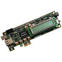
Page 9
... This section provides an overview of the Cyclone IV GX Transceiver starter board, including an annotated board image and component descriptions. provides an overview of the starter board features. © March 2010 Altera Corporation Figure 2–1 illustrates major component locations and Cyclone IV GX Transceiver Starter Kit User Cyclone IV GX Transceiver Starter Board Reference Manual 2 ...
Page 10
... FPGA device that supports active serial configuration and reloads the data to the FPGA upon power-up or reconfiguration. Chapter 2: Board Components Board Overview SMAs DC Input Jack (J4) Power LED (D12) Power Switch Character Flash x16 SSRAM x18 LCD Memory (U11) Memory (J6) (U12) Description © March 2010 Altera Corporation (SW1) ...
Page 11
... Synchronous burst mode flash device which provides a 16-MB non-volatile memory port. Provides 10/100/1000 BASE-T Ethernet connection via a Marvell 88E1111 PHY and the FPGA-based Altera Triple Speed Ethernet MegaCore function in SGMII mode. A Marvell 88E1111 PHY device for 10/100/1000 BASE-T Ethernet connection. The device is an auto-negotiating Ethernet PHY with an SGMII interface to the FPGA ...
Page 12
... Transceivers Memory (Kbits) Multipliers 540 0 Manufacturer Altera Corporation EP4CGX15BF14 Chapter 2: Board Components Featured Device: Cyclone IV GX Device Description Cyclone IV Device (2.5 Gbps) PLLs Package Type 2 3 169-pin FBGA Manufacturing Manufacturer Part Number Website www.altera.com © March 2010 Altera Corporation ...
Page 13
... Device I/O Total: Notes to Table 2–4: (1) 60 out of 72 user I/Os are bidirectional I/O pins while the other 12 pins are for clock inputs only. (2) The total I/O count excludes the transceiver bank. © March 2010 Altera Corporation Bank 6A EP4CGX15 Bank 5A (Note 1) I/O Standard ...
Page 14
... MAX II CPLD EPM2210 System Controller The board utilizes the EPM2210 System Controller, an Altera MAX II CPLD, for the following purposes: ■ FPGA configuration from flash memory ■ Power consumption monitoring ■ Virtual JTAG interface for PC-based GUI ■ Control registers for clocks Control registers for remote system update ■ ...
Page 15
... FSML_A12 FSML_A13 FSML_A14 FSML_A15 FSML_A16 FSML_A17 FSML_A18 FSML_A19 FSML_A20 FSML_A21 FSML_A22 FSML_A23 FSML_D0 FSML_D1 FSML_D2 © March 2010 Altera Corporation EPM2210 EP4CGX15BF14 Pin Number Pin Number C5 A13 FSML bus flash memory write enable M2 J5 FPGA configuration done N2 A5 FPGA configuration data M1 ...
Page 16
... FSML bus SSRAM chip enable F2 — FSML bus SSRAM address status controller F1 — FSML bus SSRAM address status processor G2 — FSML bus SSRAM address valid G1 L7 FSML bus SSRAM clock Chapter 2: Board Components MAX II CPLD EPM2210 System Controller Description © March 2010 Altera Corporation ...
Page 17
... FPGA Configuration over Embedded USB-Blaster The USB-Blaster is implemented using a USB Type-B connector (J5), a FTDI USB 2.0 PHY device (U5), and an Altera MAX II CPLD (U4). This allows the configuration of the FPGA using a USB cable directly connected between the USB port on the board (J5) and a USB port running the Quartus II software. The JTAG chain is normally mastered by the embedded USB-Blaster found in the MAX II CPLD EPM240M100 ...
Page 18
... Numonyx Chapter 2: Board Components Configuration, Status, and Setup Elements Flash 128 Mb SSRAM 18 Mb MAX II CPLD PCI Express EPM2210 (Edge Gold Finger) System Controller TCK TMS TDI TDO TCK TMS TDI TDO PCIE_JTAG_EN Device MAX II EPCS JTAG © March 2010 Altera Corporation ...
Page 19
... The secondary method is to use the pre-built parallel flash loader (PFL) design included in the starter kit. The starter board implements the Altera PFL megafunction for flash memory programming. The PFL megafunction is a block of logic that is programmed into an Altera programmable logic device (FPGA or CPLD) ...
Page 20
... EPCS programming is possible through a variety of methods. One method to program the EPCS device is to use the Serial FlashLoader (SFL), a JTAG-based in-system programming solution for Altera serial configuration devices. The SFL is a bridge design for the FPGA that uses the JTAG connector (J1) to access the JTAG Indirect Configuration Device Programming File ( ...
Page 21
... Configuration settings DIP switch ■ ■ Configuration push-button switches © March 2010 Altera Corporation Description Red LED. Illuminates when the MAX II CPLD EPM2210 System Controller fails to configure the FPGA. Driven by the MAX II CPLD EPM2210 System Controller. Green LED. Illuminates when the FPGA is successfully configured. Driven by the MAX II CPLD EPM2210 System Controller ...
Page 22
... FPGA_MSEL2 (S7.4) (S7. Chapter 2: Board Components Configuration, Status, and Setup Elements Table 2–11 shows the Default ON OFF OFF ON Manufacturer Website www.ck-components.com Table 2–11. POR FPGA_MSEL1 FPGA_MSEL0 (S7.2) (S7.1) Delay 1 1 Fast 1 0 Standard 0 0 Fast 0 0 Standard © March 2010 Altera Corporation (1) ...
Page 23
... Table 2–15 lists the configuration push-button switches component reference and manufacturing information. Table 2–15. Configuration Push-button Switches Component Reference and Manufacturing Information Board Reference Description S1-S3 Push-button switches © March 2010 Altera Corporation (Note 1) Setting EPCS_nCS FPGA_MSEL2 FPGA_MSEL1 (S7.4) (S7.3) (S7.2) ...
Page 24
... LVDS clock inputs from 125-MHz LVDS crystal oscillator depending on CLK_SEL J6 Positive and negative differential HCSL HCSL clock inputs from PCI Express J7 edge connector. Chapter 2: Board Components Clock Circuitry 125 MHz LVDS SMA LVDS SMA Source-Select Switch Description © March 2010 Altera Corporation ...
Page 25
... Cyclone IV GX device. The LEDs illuminate when a logic 0 is driven, and turns off when a logic 1 is driven. There is no board-specific function for these LEDs. Table 2–19 lists the user-defined LED schematic signal names and their corresponding Cyclone IV GX pin numbers. © March 2010 Altera Corporation “Configuration Push-Button Switches” on Schematic Signal Name USER_PB0 ...
Page 26
... FSML_D3 FSML_D4 FSML_D5 FSML_D6 FSML_D7 LCD_CSn Chapter 2: Board Components General User Input/Output Cyclone IV GX Device Pin Number N8 C13 N5 M6 Manufacturer Website www.lumex.com Cyclone IV GX Device Pin Number N4 A6 D11 D12 E10 F9 E13 F10 F11 G9 L9 © March 2010 Altera Corporation ...
Page 27
... This interface uses the Cyclone IV GX device's PCI Express hard IP block, saving logic resources for the user logic application. f For more information on using the PCI Express hard IP block, refer to the Compiler User © March 2010 Altera Corporation Symbol Level V — ...
Page 28
... I/O Standard PCIE_TX_P PCIE_TX_N 1.4-V PCML PCIE_RX_P PCIE_RX_N PCIE_REFCLK_P HCSL PCIE_REFCLK_N LVTTL PCIE_PERSTn — PCIE_PRSNTn_x1 — PCIE_PRSNTn_x1 PCIE_JTAG_TCK PCIE_JTAG_TDI 3.3-V PCIE_JTAG_TDO PCIE_JTAG_TMS © March 2010 Altera Corporation Chapter 2: Board Components Cyclone IV GX Device Pin Number A10 — — — — — — ...
Page 29
... The device is an auto-negotiating Ethernet PHY with an SGMII interface to the FPGA. The MAC function must be provided in the FPGA for typical networking applications such the Altera Triple Speed Ethernet MegaCore design. The Marvell 88E1111 PHY uses 2.5-V and 1.2-V power rails and requires a 25-MHz reference clock driven from a dedicated oscillator ...
Page 30
... Populate R53 and R52 ■ Unpopulate R54 and R51 (default) ■ Populate C60 and C57 ■ Unpopulate C59 and C58 ■ Populate R54 and R51 ■ Unpopulate R53 and R52 ■ Chapter 2: Board Components Memory Multiplexer Location © March 2010 Altera Corporation ...
Page 31
... Data bus U12.13 Data bus U12.18 Data bus U12.19 Data bus U12.22 Data bus U12.23 Data bus U12.86 Output enable © March 2010 Altera Corporation Schematic Signal Name I/O Standard FSML_A1 FSML_A2 FSML_A3 FSML_A4 FSML_A5 FSML_A6 FSML_A7 FSML_A8 FSML_A9 FSML_A10 FSML_A11 ...
Page 32
... SRAM_CLK SRAM_CE2 SRAM_CE3n SRAM_GWn SRAM_MODE SRAM_ZZ Manufacturing Manufacturer Part Number ISSI Inc. IS61VPS102418A-250TQL Guide. Chapter 2: Board Components Memory Cyclone IV GX Device Pin Number — — — — — — — — Manufacturer Website www.issi.com Cyclone IV GX © March 2010 Altera Corporation ...
Page 33
... Data bus U11.47 Data bus U11.49 Data bus U11.51 Data bus U11.53 Data bus U11.35 Data bus U11.37 Data bus © March 2010 Altera Corporation Schematic Signal Name I/O Standard FLASH_CEn FSML_OEn FLASH_RESETn FSML_WEn FLASH_WPn FSML_A1 FSML_A2 FSML_A3 FSML_A4 FSML_A5 FSML_A6 ...
Page 34
... Schematic Signal Name I/O Standard FSML_D10 FSML_D11 FSML_D12 2.5-V FSML_D13 FSML_D14 FSML_D15 Manufacturing Manufacturer Part Number Numonyx JS28F128P33BF © March 2010 Altera Corporation Chapter 2: Board Components Power Supply Cyclone IV GX Device Pin Number A11 B11 B10 C11 C12 C8 Manufacturer Website www.numonyx.com ...
Page 35
... V(0.705 A) Table 2–32 lists the power supply component reference and manufacturing information. Table 2–32. Power Supply Component Reference and Manufacturing Information Board Reference Description — 16-V power supply © March 2010 Altera Corporation 5V_USB 0.066 A 5.0 V 0.042 A 0. BEAD R BEAD 2.5 V ...
Page 36
... FPGA core voltage and PCI Express hard IP VCCINT block power 1.2 FPGA PLL digital power VCCD_PLL Chapter 2: Board Components Power Supply Embedded USB-Blaster To User PC Power GUI USB MAX II CPLD EPM240M100 PHY JTAG Chain MAX II CPLD EPM2210 System Controller Description clock input pins IO © March 2010 Altera Corporation ...
Page 37
... SJ/T11363-2006 standard. (2) X* indicates that the concentration of the hazardous substance of at least one of all homogeneous materials in the parts is above the relevant threshold of the SJ/T11363-2006 standard, but it is exempted by EU RoHS. © March 2010 Altera Corporation Manufacturer Notes Hexavalent ...
Page 38
... Cyclone IV GX Transceiver Starter Board Reference Manual Chapter 2: Board Components Statement of China-RoHS Compliance © March 2010 Altera Corporation ...
Page 39
... Contact Technical support Technical training Product literature Non-technical support (General) Email (Software Licensing) Email Note to Table: (1) You can also contact your local Altera sales office or sales representative. © March 2010 Altera Corporation Changes Made Contact (Note 1) Method Website www.altera.com/support Website www ...
Page 40
... A warning calls attention to a condition or possible situation that can cause you injury. The angled arrow instructs you to press Enter. The feet direct you to more information about a particular topic. Preliminary Additional Information Typographic Conventions © March 2010 Altera Corporation ...