ATJTAGICE2 - JMS2206 Atmel, ATJTAGICE2 - JMS2206 Datasheet - Page 2
ATJTAGICE2 - JMS2206
Manufacturer Part Number
ATJTAGICE2 - JMS2206
Description
TEST BOARD KIT, COMBO
Manufacturer
Atmel
Datasheet
1.ATJTAGICE2_-_JMS2206.pdf
(5 pages)
Specifications of ATJTAGICE2 - JMS2206
Svhc
No SVHC (15-Dec-2010)
Development Tool Type
Development Kit
Kit Features
Supports Debugging With AVR Traditional JTAG Interface And With DebugWIRE Interface
Mcu Supported Families
AVR Microcontroller
Silicon Manufacturer
Atmel
Core Architecture
AVR
Core Sub-architecture
AVR UC3
Kit Contents
Board
Features
Integral 5-volt Linear Regulator, LED DC On Indicator
Rohs Compliant
Yes
Lead Free Status / RoHS Status
Lead free / RoHS Compliant


Enabling debugWIRE interface with JTAGICE mkII
2
AVR JTAGICE mkII
The connection between the JTAGICE mkII probe and the 6-pin header on the target is
described in Table 1.
Table 1. Connections required for ISP and debugWIRE
Once the DWEN fuse is programmed by ISP, there is only need for the GND, VTref, and
RESET lines when using the debugWIRE interface, thus the JTAGICE mkII will set lines
TCK, TDO and TDI to high impedance. The user can choose whether to disconnect the
three unused lines.
Note:
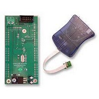
Figure 2. Connecting JTAGICE mkII probe to 6-pin ISP header using the squid cable
Enabling the debugWIRE interface is either done via ISP or High-Voltage programming.
JTAGICE mkII supports DWEN handling via ISP only.
Connect the JTAGICE mkII to the target. When starting a debugWIRE debugging ses-
sion, the JTAGICE mkII assumes that debugWIRE is enabled. If debugWIRE is not
enabled (DWEN fuse disabled), a dialog window in AVR Studio will offer you to enable
the interface via JTAGICE mkII. Note that this requires all six pins connected as
described in Table 1. Once the DWEN fuse is programmed, only three pins are needed
for further debugging the microcontroller.
JTAGICE mkII probe
Pin 1 (TCK)
Pin 2 (GND)
Pin 3 (TDO)
Pin 4 (VTref)
Pin 6 (nSRST)
Pin 9 (TDI)
Some precautions regarding the RESET line should be taken to ensure proper communi-
cation via the debugWIRE interface. Pull-up resistors on the RESET line must not be
smaller than 10KΩ (the pull-up resistor is not required for debugWIRE functionality), and
there should be no capacitive load (besides the one created by the line itself). Other logic
connected to the RESET line should be removed during debugging.
ISP6PIN header
Pin 3 SCK
Pin 6 GND
Pin 1 MISO
Pin 2 V
Pin 5 RESET
Pin 4 MOSI
CC
ISP
x
x
x
x
x
x
debugWIRE
2562C–AVR–07/06
x
x
x
Related parts for ATJTAGICE2 - JMS2206
Image
Part Number
Description
Manufacturer
Datasheet
Request
R

Part Number:
Description:
AVR ON-CHIP D-BUG SYSTEM
Manufacturer:
Atmel
Datasheet:

Part Number:
Description:
JTAG EMULATOR FOR AVR
Manufacturer:
Atmel
Datasheet:

Part Number:
Description:
DEV KIT FOR AVR/AVR32
Manufacturer:
Atmel
Datasheet:

Part Number:
Description:
INTERVAL AND WIPE/WASH WIPER CONTROL IC WITH DELAY
Manufacturer:
ATMEL Corporation
Datasheet:
Part Number:
Description:
Low-Voltage Voice-Switched IC for Hands-Free Operation
Manufacturer:
ATMEL Corporation
Datasheet:
Part Number:
Description:
MONOLITHIC INTEGRATED FEATUREPHONE CIRCUIT
Manufacturer:
ATMEL Corporation
Datasheet:
Part Number:
Description:
AM-FM Receiver IC U4255BM-M
Manufacturer:
ATMEL Corporation
Datasheet:
Part Number:
Description:
Monolithic Integrated Feature Phone Circuit
Manufacturer:
ATMEL Corporation
Datasheet:
Part Number:
Description:
Multistandard Video-IF and Quasi Parallel Sound Processing
Manufacturer:
ATMEL Corporation
Datasheet:
Part Number:
Description:
High-performance EE PLD
Manufacturer:
ATMEL Corporation
Datasheet:
Part Number:
Description:
8-bit Flash Microcontroller
Manufacturer:
ATMEL Corporation
Datasheet:
Part Number:
Description:
2-Wire Serial EEPROM
Manufacturer:
ATMEL Corporation
Datasheet: