CME-8GB60 AXIOM, CME-8GB60 Datasheet - Page 12
CME-8GB60
Manufacturer Part Number
CME-8GB60
Description
Microprocessor Development Tool
Manufacturer
AXIOM
Datasheet
1.CME-8GB60.pdf
(19 pages)
Specifications of CME-8GB60
Silicon Manufacturer
Freescale
Core Architecture
HC08
Features
SPI And IIC Serial Ports, Regulated +3.3V Power Supply, Analog Or PTB I/O Port
Silicon Core Number
MC9S08GB60
Silicon Family Name
68HC08
Rohs Compliant
No
Lead Free Status / RoHS Status
Contains lead / RoHS non-compliant


M 6 8 E V B 9 0 8 G B 6 0
USER_ENABLE Switch
The USER ENABLE switch provides a method to enable or connect user components applied
to the HCS08 I/O ports. The development board user should be familiar with the input and
output application so that port conflicts do not occur. Following is the connection reference
table:
Note: LED indicators are active logic low.
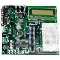
LCD DISPLAY and PORT
A 32 character (2 x 16) LCD display is provided on the development board for applications that
require this type of display output. Display I/O operation is enabled by the USER ENABLE
switch position 4 in the ON position. An optional LCD PORT is located under the display so
that the provided display can be replaced by a smaller or larger version by the user.
CONTRAST adjustment is provided to allow the use of extended temperature displays also.
Operation of the LCD display or port is in nibble or 4 bits wide data mode. The HCS08 I/O
ports PTG3 – PTG7 and PTE6 –PTE7 provide the data and control signals.
commands or data should be formatted to provide low nibble (LSB bits of byte value) on first
transaction then high nibble (MSB bits of byte value) on the second transaction. Example
software driver is provided on the support CD to assist the user in applying this device.
The following table reflects the I/O port pin application to the LCD Port:
PTG4
PTG5
PTG6
PTG7
PTG3
PTE6
PTE7
Note 1: Normally the display is always written to: PTG4-7 Data = outputs and PTG3 R/W = 0.
Caution must be observed if the display is to be Read so that the PTG4-7 data lines are set for
INPUT mode prior to the PTG3 R/W signal being set to 1. Port contention will occur if the
sequence is violated.
HCS08 PORT PIN
ENABLE
USER
1
2
3
4
5
6
7
8
4 Position DIP Switch
SW1 to SW4
RV1 Potentiometer
LCD PORT
LED 1
LED 2
LED 3
LED 4
USER COMPONENT
DB4
DB5
DB6
DB7
Read/Write* (R/W)
Register Select (RS)
Enable (EN)
LCD PORT SIGNAL
PTB4/AD4 – PTB7/AD7
PTA4 /KBD4 – PTA7/KBD7
PTB0/AD0
PTG3 – PTG7 and PTE6 – PTE7
PTF0
PTF1
PTF2
PTF3
HCS08 PORT
Bi-directional data bit (LSB)
Bi-directional data bit
Bi-directional data bit
Bi-directional data bit (MSB)
Output only, 0 = Write, 1 = Read *See Note 1
Output only, 0 = idle, 1 = active
Output only, 0 = Command, 1 = Data
12
DIRECTION
See LCD Port
operation
PORT
Output
Output
Output
Output
Input
Input
Input
NOTES
0 2 / 1 7 / 0 6
ALTERNATE PORT
MCU 31-32, 51-54, 56
ANALOG 5 - 8
ANALOG 1
MCU 1 – 4
MCU 47
MCU 48
MCU 45
MCU 46
Display
Related parts for CME-8GB60
Image
Part Number
Description
Manufacturer
Datasheet
Request
R


Part Number:
Description:
Microprocessor Development Tool
Manufacturer:
AXIOM
Datasheet:

Part Number:
Description:
CMD-5XX MOTHERBOARD ONLY
Manufacturer:
AXIOM
Datasheet:
