CME12BC32 AXIOM, CME12BC32 Datasheet
CME12BC32
Specifications of CME12BC32


Related parts for CME12BC32


CME12BC32 Summary of contents
Page 1
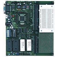
CME-12B/BC Development Board for Motorola 68HC12B32 and 68HC12BC32 Microcontrollers xiom anufacturing 2000 2813 Industrial Ln. Garland, TX 75041 (972) 926-9303 FAX (972) 926-6063 email: Gary@axman.com web: http://www.axman.com ...
Page 2
GETTING STARTED ............................................................................................3 Installing the Software..................................................................... 3 Board Startup .................................................................................. 3 Support Software ............................................................................ 4 Software Development .................................................................... 4 TUTORIAL............................................................................................................5 Creating source code ...................................................................... 5 Assembling source code ................................................................. 6 Running your application ................................................................ 7 Programming Flash EEPROM......................................................... 8 MEMORY ...
Page 3
... Follow the steps in this section to get started quickly and verify everything is working correctly. Installing the Software 1. Insert the Axiom 68HC12 support disk in your PC. If the setup program does not start, run the file called "SETUP.EXE" on the disk. 2. Follow the instructions on screen to install the support software onto your PC. ...
Page 4
... CME-12B/BC, such as the D-Bug12 and information from your own programs that send output to the serial port. Also on the disk is a free assembler, example source code, and other tools to get you started. Software Development Software development on the CME12B32 can be performed using either the DBUG12 monitor utility installed in EPROM (sockets U6/U7), the DBUG12 monitor programmed into the internal Flash EPROM or a Background Debug Module (BDM) connected to the BDM-IN connector ...
Page 5
This section was written to help you get started developing software with the CME-12B/BC board. Be sure to read the rest of this manual as well as the documentation on the disk if you need further information. The following sections ...
Page 6
... If you prefer a windows integrated programming environment – try the Motorola MCU-EZ tools. Refer to the MCU-EZ documentation on the disk for more information. Also, a port for the free GNU C compiler and tools for the HC12 is in the works and may be finished as you read this. Check www.axman.com or : http://home ...
Page 7
After creating an S-Record file you can "upload" the development board for a test run. The provided example “HELLO.ASM” was created to run from RAM so you can use the D- Bug12 Monitor to test it without programming ...
Page 8
You can program your application into EEPROM so it executes automatically when you apply power to the board as follows: 1. Make a backup copy of HELLO.ASM then use a text editor to modify it. Change the start of the ...
Page 9
Following is the default memory map for this development board. Consult the HC12 technical reference manual on the support disk for details of the internal memory map for the processor. FFFF FFFE - - - - - CONFIG SWITCH 1 ...
Page 10
The CME-12B/BC board is shipped from the manufacturer with the following default CONFIG SWITCH settings The 8 position CONFIG SWITCH provides an easy method of configuring the CME-12B/BC32 board operation. Following are the configuration ...
Page 11
LCD_PORT The LCD_PORT interface is connected to the data bus and memory mapped to locations 270 – 27F hex assigned to CS7. For the standard display, address 270 is the Command register, address 271 is the Data register. The interface ...
Page 12
The MCU_PORT provides access to the peripheral features and I/O lines of the HC12 as follows: A14 1 2 A15 /XIRQ 11 12 /DBE ...
Page 13
The COM-1 port has a Female DB9 connector that interfaces to TXD0 2 6 the HC12 internal SCI0 serial port. It uses a simple 2 wire RXD0 3 7 asynchronous serial interface GND 5 9 Pins 1, ...
Page 14
The BDM-IN port pin header compatible in pinout with the Motorola Background Debug Mode (BDM) Pod. This allows the connection of a background debugger for software development, programming and debugging in real-time, since the BDM control logic ...
Page 15
The CME-12B/BC board is fully tested and operational before shipping fails to function properly, inspect the board for obvious physical damage first. Ensure that all IC devices in sockets are properly seated. Verify the communications setup as described ...
Page 16
Following are a number of tips, suggestions and answers to common questions that will solve many problems users have with the CME-12B/BC development system. You can download the latest software from the Support section of our web page at: www.axman.com ...
Page 17
TABLE 1. LCD Command Codes Command codes are used for LCD setup and control of character and cursor position. All command codes are written to LCD panel address $B5F0. The BUSY flag (bit 7) should be tested before any command ...
Page 18
ASM <Address> <CR> <.> BAUD <baudrate> BF <StartAddress> <EndAddress> [<data>] BR [<Address>] BULK CALL [<Address>] DEVICE [<DevName> [<Address>...<Address>]] EEBASE <Address> FBULK FLOAD [<AddressOffset>] G [<Address>] GT <Address> HELP LOAD [<AddressOffset>] MD <StartAddress> [<EndAddress>] MDW <StartAddress> [<EndAddress>] Memory Display Words MM ...