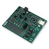
RS08KA2 PROMO Freescale Semiconductor, RS08KA2 PROMO Datasheet - Page 27

RS08KA2 PROMO
Manufacturer Part Number
RS08KA2 PROMO
Description
DEMO KIT, SILICON BUNDLE, RS08KA2
Manufacturer
Freescale Semiconductor
Datasheet
1.RS08KA2_PROMO.pdf
(34 pages)
Specifications of RS08KA2 PROMO
Kit Contents
DEMO9RS08KA2 Board, USB Cable, Quick Start Guide, User Manual, Packing List
Svhc
No SVHC (15-Dec-2010)
Development Tool Type
Demonstration Kit
Kit Features
RS08KA2 Microcontroller,
Silicon Manufacturer
Freescale
Core Architecture
RS08
Core Sub-architecture
RS08
Silicon Core Number
MC9RS08
Silicon Family Name
RS08KA
Rohs Compliant
Yes
Lead Free Status / RoHS Status
Lead free / RoHS Compliant
2.2
The emulated ADC performance depends highly on the RC network time constant accuracy. If the actual
RC component values deviates from their specified values, the RC charging profile will be shifted and the
timer capture will be inaccurate. In addition, variations in parasitic loading on the PCB layout will also
contribute to RC time constant error. Simple calibration can be performed to compensate for the change in
RC constant.
To measure the actual RC constant the charging profile must be recorded. This can be done by applying a
V
RC network to reach V
calculation listed in
do the calibration.
Freescale Semiconductor
DD
•
•
•
/2 voltage to the ADC input. The charging profile is recorded as in
From
Instead of using fixed value R or C, variable R or C component can be used. Adjusting the R or
the C until the rise time is reduced to the expected value (152µs in this case).
Compensation can be done by adjusting the timer resolution. MC9RS08KA2 and many Freescale
MCUs include a software programmable clock source (ICS), bus frequency can be fine-tuned by
simply reprogramming the content of the TRIM register. In this example, timer resolution is 4µs
based on the previous calculation with 2MHz bus frequency, 38 timer counts are expected to reach
V
divided by 38, i.e. 6.94µs. With a divide-by-8 prescaler option selected for the timer clock source,
compensated bus period should be 6.94µs divided by 8, which is 868ns, i.e. 1.15MHz bus
frequency. Therefore, if a 1.15MHz bus frequency is used, no hardware adjustment nor lookup
table modification is required. For MC9RS08KA2, bus frequency can be changed by
reprogramming the TRIM register and bus frequency divider bits in the ICSC2 register. (Refer to
MC9RS08KA2 data sheet for more details.)
DD
Calibration
/2 voltage level. So, with 264µs measured rise time, new timer resolution should be 264µs
Equation 2
Table 2-7
DD
it is possible to deduce the actual RC constant and rebuild the lookup table.
/2 voltage level, 264µs in this case. The expected rise time based on the previous
is 152µs, which is equivalent to 38 timer counts. There are several ways to
Figure 2-7. 2.5V Input R-C Charging Profile
Getting Started with RS08, Rev. 1
264ms
Figure
Emulated ADC Application Example
V
DD
/2
2-7. The time taken for the
27


