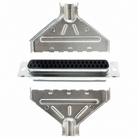
1658651-1 Tyco Electronics, 1658651-1 Datasheet

1658651-1
Specifications of 1658651-1
Related parts for 1658651-1
1658651-1 Summary of contents
Page 1
... Removed old logos from artwork. S Updated document to corporate requirements. S E2011 Tyco Electronics Corporation Connectivity Ltd. Company All Rights Reserved *Trademark TE Connectivity, TE connectivity (logo), and TE (logo) are trademarks. Other logos, product and/or Company names may be trademarks of their respective owners. Connector ...
Page 2
Customer Assistance Reference Part Number 205206 and Product Code 5091 are representative numbers of AMPLIMITE HDP--20 Subminiature D Commercial Connectors. Use of these numbers will identify the product line and expedite your inquiries through a service network established to ...
Page 3
Document Number Document Title 408--9507 Crimping Die Assemblies 543424--1 Through --8 for AMPLIMITE Connectors 408--9508 Crimping Die Assemblies 543425--1 and 543425--2 for AMPLIMITE Connectors 408--9721 Die Holder Assemblies 58449--1, --2, and --3 409--5842 AMP--O--LECTRIC* Model “G” Terminating Machine 354500--[ ] ...
Page 4
CONNECTOR PANEL POSITIONS POSITIONS FLOATING FLOATING MTG MTG AND BUSHING POSN SHELL SIZE Yes Front Front 9 Position No Yes Size 1 Rear Rear No Yes Front Front 15 Position No Yes Size 2 Rear Rear No Yes Front Front ...
Page 5
Contact Insertion Terminated contacts are inserted into the back of the connector housing, and snap in place. The cavity rows are numbered for your convenience. If your design does not require the use of all cavities, the contacts should ...
Page 6
CABLE DIAMETER ACCEPTED 4.19--4.83 [.165--.190] 4.83--5.51 [.190- - .217] 5.51--6.25 [.217--.246] 6.25--7.21 [.246--.284] 7.21--8.23 [.284- - .324] 8.23--9.52 [.324--.375] 9.52--11.10 [.375--.437] 10.16--11.56 [.400--.455] 5.84--6.73 [.230--.265] 8.58--9.78 [.338--.385] 9.52--10.97 [.375--.432] 10.72--12.45 [.422--.490] 12.19--14.27 [.480--.562] 3.6. Hardware and Accessories The AMPLIMITE HDP--20 ...
Page 7
F. Universal Cable Clamp Kits Universal Cable Clamp Kits (Instruction Sheet 408--9238) are available for connectors with a number 3 shell size (25 position) only. Each kit consists of two cable clamp halves, a two--piece braid termination clamp set (shielded ...
Page 8
Receptacle (Ref) Plug Spring (Ref) Latch (2) Latching Block (2) M3 Metric Screw (2) Cable Clamp Assembly with Screwlocks and Retainers Assembled Screwlock (Ref Fillister Head Screws and Hex Nuts (2 Each) Connector Straight Exit RFI/EMI Shielded ...
Page 9
Crimp Ferrules for Flared Braided Cable Shield Braid Inner Ferrule Conductors Foil or Braid (To be Folded Back Over Split- Ring Ferrules or Foil Ferrule and Ground or Braided Cable Shield Wire) Conductors One- Piece Slide Latch J Assembly Kit ...
Page 10
Repair Use Insertion/Extraction Tool 91285--1 (Instruction Sheet 408--9404) to remove individual contacts from housings for replacement or for relocation to another housing cavity. Damaged or worn contacts may be replaced provided there is sufficient slack, after restripping the wire, ...
Page 11
CONNECTOR CABLE OR CABLE CLAMP DIAMETER SHELL SIZE ACCEPTED 4.83--6.10 [.190--.240] 5.84--7.11 [.230--.280] 25 Position 25 Position 300 350] 7.62--8.89 [.300--.350] Si Size 380 430] 9.65--10.92 [.380--.430] 11.94--13.46 ...
Page 12
Miscellaneous Tooling Shielding Enclosure Expansion Tool 58241 5.2. Single Cable- to- Shield Ferrules The dies listed in the table in Figure 7 must be inserted into the hand tools and automatic machine die holder that uses them. ...
Page 13
VISUAL AID Figure 8 shows a typical application of an AMPLIMITE HDP--20 Subminiature D Commercial Connector with Snap--In Contacts. This illustration should be used by production personnel to ensure a correctly applied product. Applications which DO NOT appear correct ...


