H-Q-5-KIT CONTACT CONNECTORS, H-Q-5-KIT Datasheet - Page 11
H-Q-5-KIT
Manufacturer Part Number
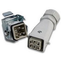
H-Q-5-KIT
Description
CONNECTOR KIT, TOP ENTRY, HQ5
Manufacturer
CONTACT CONNECTORS
Series
EPIC HBSr
Datasheet
1.15.1238.pdf
(363 pages)
Specifications of H-Q-5-KIT
Connector Type
Rectangular
Gender
Plug, Socket
No. Of Contacts
5
No. Of Rows
2
Contact Gender
Male, Female
Connector Mounting
Cable Mount
Connector Shell Size
HQ 5
Contact
RoHS Compliant
Contact Termination
Crimp
Rohs Compliant
Yes


Technical
Technisches Vorwort / Technical Considerations / Préambule technique
C O N S I D E R A T I O N S
Cable Gland:
When the correct cable gland is selected to match the cable diameter a
good seal is ensured. Cable Glands are available to fulfill many additional
requirements. A gland with a saddle clamp supplies good strain relief or
one with a neoprene boot offers anti-kinking. These devices help to pre-
vent damage to the connection or the cable. In addition cable glands are
avialable for use with cables improving EMC performance by taking the
screen to the body of the connector.
Male and Female Inserts:
(NB: Information regarding materials is provided on the following pages)
The male and female inserts are the receptacles for the male and female
contacts respectively, and is the interface for the electrical connection. Ca-
ble is terminated to the contacts. Inserts provide the electrical insulation.
Contact types:
(NB: Information concerning materials/contact coatings is provided on the
following pages)
Screw termination:
This simple type of termination is distinguished by its ease of maintenan-
ce. No special tool is required, just a screwdriver to undo and to tighten up
the terminal screws.
Screw connection technology (as per DIN 0609)
Conductor section (mm
Screw thread:
Test torque Nm:
Crimp termination:
The purpose of crimping is to produce a good mechanical, electrical and
gas-tight connection. This should remain unchanged with regard to quality
in the long-term, and should thus be reliable.
Crimping also reduces termination time and allows the designer to achieve
more connections than screw termination would permit in the same space
Hand-operated tools or crimping machines can be used to assemble
crimp contacts. The following points must be harmonised with each other
in order to obtain the ideal crimping result:
• Cross section dimension/gauge size and structure of the cable
• Contact type and size
• Tool and tool setting
There are two different contact types: - Machined and Stamped. These
two types of contact have differing characteristics in terms of quality and
how the termination is made.
Stamped contacts: The crimping sleeve allows a wider range of wire gua-
ges to be crimped. This guarantees reliable crimping quality. Furthermore,
the insertion and extraction force is usually lower with stamped pin and
socket contacts. This is achieved by the large contact area and the spring
characteristics of the stamped contact’s material. Stamped contacts can
be supplied on a bandolier for use with automatic feed crimping tools.
Machined contacts: With this popular type of contact, the suitable contact
size is matched to the wire gauge of the cable. The correct crimping tool
or die must be used.
Cage Clamp termination:
This type of termination is noted for its ease and speed of fitting without
an additional tool. The compensating effect of the cage clamp enables
good contact to be maintained in the long term.
2
) 1
M 2,6 M 3
40
1,5
50
2,5
M 3
50
4
M 3,5 M 4
80
6
120
10
M 4
120
23
Related parts for H-Q-5-KIT
Image
Part Number
Description
Manufacturer
Datasheet
Request
R

Part Number:
Description:
CONTACT, SOCKET, IDC / IDT
Manufacturer:
TE Connectivity
Datasheet:

Part Number:
Description:
CONTACT, PIN, 26-22AWG, CRIMP
Manufacturer:
TE Connectivity
Datasheet:

Part Number:
Description:
CONTACT, SOCKET, IDC / IDT
Manufacturer:
TE Connectivity
Datasheet:

Part Number:
Description:
CONTACT, RECEPTACLE, AWG20-15.5
Manufacturer:
TE Connectivity
Datasheet:

Part Number:
Description:
CONTACT, PIN, AWG18.5-15.5
Manufacturer:
TE Connectivity
Datasheet: