131-8701-261 JOHNSON/EMERSON, 131-8701-261 Datasheet - Page 2
131-8701-261
Manufacturer Part Number
131-8701-261
Description
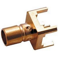
RF/COAXIAL, SMB JACK, STR, 75OHM, SOLDER
Manufacturer
JOHNSON/EMERSON
Datasheet
1.131-8701-261.pdf
(2 pages)
Specifications of 131-8701-261
Body Style
Straight Jack
Coaxial Termination
Solder
Rg Cable Type
RG-59, 179
Contact Material
Beryllium Copper
Contact Plating
Gold
Connector Type
SMB Coaxial
Impedance
75ohm
Lead Free Status / RoHS Status
Lead free / RoHS Compliant


Plug
Mini-75 Ohm SMB Connectors
Specifications
ELECTRICAL RATINGS
Impedence: 75 ohms
Frequency Range: 0-2 GHz
VSWR: f = GHz
RG-179, RG-59, Belden 735A cable:
Adapters .......................................................................................... 1.20 + .04f
Type N Adapters ............................................................................. 1.05 +. 01f
Matching pad 50 ohm/75 ohm .......................................................... 1.05 + .1f
Loads .............................................................................................. 1.05 + .01f
Uncabled receptacles, opens, shorts ......................................................... N/A
Working Voltage: (Vrms maximum)†
Connectors for Cable Type
Dielectric Withstanding Voltage: (VRMS minimum at sea level)†
Connectors for RG-179, RG-59, Belden 735A,
Corona Level: (Volts minimum at 70,000 feet)†
Uncabled receptacles, adapters, open, shorts, loads, matching pad: N/A
Electrical Length: Open + 1.5
Insertion Loss: (dB maximum, tested at 1.5 GHz)
Insulation Resistance: 1000 megohms minimum
Contact Resistance: (milliohms maximum)
Center contact (straight cabled connectors,
Center contact (right angle cabled
Outer contact (gold plated connectors) ................... 1.0
Outer contact (nickel plated connectors) ................ 2.5
Braid to body (gold plated connectors) ................... 1.0
Braid to body (nickel plated connectors) ................. 2.5
RF Leakage: (dB minimum tested at 2.5 GHz)
RF High Potential Withstanding Voltage: (Vrms minimum, tested at
RG-179, RG-59, Belden 735A,
Open, shorts, loads, matching pad .......................... N/A
Open, shorts, loads, matching pad ......................................................... N/A
Connectors for RG-179, RG-59, Belden 735A ....................................... 250
Straight cable connectors ............................................................... 0.30 dB
Right angle cable connectors ......................................................... 0.60 dB
Matching pad .......................................................................... 6 dB nominal
Uncabled receptacles, adapters, opens, shorts, loads .......................... N/A
uncabled receptacles, opens, shorts, loads) ....... 6.0
Cable connectors .............................................................................. -55 dB
Uncabled receptacles, adapters opens, shorts, loads,matching pad...N/A
4 and 7 MHz)†
Connectors for RG-179, RG-59, Belden 735A ....................................... 700
Uncabled receptacles and adapters ....................................................... 600
Opens, shorts, loads, matching pad ....................................................... N/A
Johnson Components
connectors and adapters) .................................. 12.0
uncabled receptacles, adapters ........................... 335
uncabled receptacles, adapters ........................................................ 1000
MATING ENGAGEMENT FOR MINI-75 OHM SMB SERIES (INTERMATABLE WITH STANDARD 50 OHM SMB)
Short + 1.5
Adapters + 5.2
Straight cabled connectors ............................ 1.25 + .04f
Right angle cabled connectors ...................... 1.35 + .04f
TM
• P.O. Box 1732 • Waseca, MN 56093-0832 • 1-800-247-8256 • Fax: 507-833-6287 • www.johnsoncomponents.com
o
o
(+ 5.2
(+ 5.2
o
(N/A for Jack-Bulkhead Jack and N Types)
o
o
relative to short)
relative to open)
Jack
Initial
Sea Level
P l u g
P l u g
P l u g
P l u g
P l u g
Environmental
70K Feet
After
16.0
N/A
N/A
8.0
1.5
3.5
N/A
85
** All gold plated parts include a .00005" min. nickel underplate barrier layer.
Power Rating: (Loads and matching pad only) 1.0 watt at +25 C derated
linearly to .5 watt at +125 C
MECHANICAL RATINGS
Engagement Design: MIL-C-39012, Series SMB
Engagement/Disengagment Force: 2 pounds minimum to
Contact Retention: 4 lbs. minimum axial force (captivated contacts)
Cable Retention:
Connectors for RG-179, Belden 735A ............... 20
Connectors for RG-59 ........................................ 40
* or cable breaking strength whichever is less.
Durability: 500 cycles minimum
ENVIRONMENTAL RATINGS (Meets or exceed the applicable paragraph
of MIL-C-39012)
Temperature Range: - 65 C to +165 C -- Connectors and adapters
Thermal Shock: MIL-STD-202, Method 107, Condition B
Corrosion: MIL-STD-202, Method 101, Condition B
Shock: MIL-STD-210, Method 213, Condition B
Vibration: MIL-STD-202, Method 204, Condition B
Temperature Coefficient: (Loads only) + 300 ppm/ C
MATERIAL SPECIFICATIONS
Bodies: Brass per QQ-B-626, gold plated** per MIL-G-45204 .00001" min.
Contacts: Male & Female - beryllium copper per QQ-C-530, gold plated per
Insulators: PTFE fluorocarbon per ASTM D 1710 and ASTM D 1457
Expansion Caps: Brass per QQ-B-613, gold plated per MIL-G-45204
Crimp Sleeves: Copper per WW-T-799, gold plated per MIL-G-45204
Mounting Hardware: Brass (nuts) per QQ-B-626 or phosphor bronze
Avoid user injury due to misapplication. See safety advisory definitions inside front cover.
or nickel plated per QQ-N-290
N type adapters stainless steel per QQ-S-763, passivated per
MIL-F-14072
MIL-G-45204 .00003" min.
.00001" min. or nickel plated per QQ-N-290
.00001" min. or nickel plated per QQ-N-290
(lockwashers) QQ-B-750, gold plated per MIL-G-45204 .00001" min. or
nickel plated per QQ-N-290
(N/A opens, shorts, loads, matching pad)
(N/A opens, shorts, loads, matching pad)
(N/A opens, shorts, loads, matching pad)
(N/A opens, shorts, loads, matching pad)
1 inch-ounce minimum torque (uncabled receptacles)
- 65 C to +125 C -- Loads, matching pad
20 C to 26 C -- Opens, shorts
Jack
14 pounds maximum axial force
INCHES (MILLIMETERS)
CUSTOMER DRAWINGS AVAILABLE UPON REQUEST
Axial Force*
(pounds)
NOTES:
1. ID of contact to meet
2. Must meet the force to
VSWR, mating charac-
teristics and connector
durability when mated
with a dia .019-.021
(0.48/0.53) male con-
tact.
engage and disengage
when mated with mating
part.
Torque
(in-oz)
N/A
N/A
Related parts for 131-8701-261
Image
Part Number
Description
Manufacturer
Datasheet
Request
R

Part Number:
Description:
RF/COAXIAL SMB BHD JACK STR 75OHM SOLDER
Manufacturer:
JOHNSON/EMERSON
Datasheet:

Part Number:
Description:
RF/COAXIAL, SMB JACK, R/A, 75OHM, SOLDER
Manufacturer:
JOHNSON/EMERSON
Datasheet:

Part Number:
Description:
131,072-word X 8-bit High Speed CMOS Static RAM
Manufacturer:
HITACHI
Datasheet: