67.9760-23 MULTI-CONTACT, 67.9760-23 Datasheet - Page 32
67.9760-23
Manufacturer Part Number
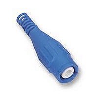
67.9760-23
Description
PLUG, BNC, RG58/50R, BLUE
Manufacturer
MULTI-CONTACT
Datasheet
1.67.9799-21.pdf
(40 pages)
Specifications of 67.9760-23
Coaxial Termination
Solder / Crimp
Rg Cable Type
RG-58
Contact Material
Brass
Contact Plating
Gold
Frequency Max
3GHz
Connector Mounting
Cable Mount
Connector Type
BNC, Coaxial
Impedance
50ohm
Lead Free Status / RoHS Status
Lead free / RoHS Compliant


Technische Informationen
Tastköpfe – unverzichtbares
Zubehör eines Oszilloskops
Das Oszilloskop ist eines der wichtigsten Mess-
geräte in der Elektronik. Ständige Weiterent-
wicklungen haben die Leistung dieser Geräte
erheblich gesteigert und deren Einsatzmöglich-
keiten vergrößert. Um ein Messsignal auf die-
sen Geräten darstellen zu können, ist eine
Leitungsverbindung zwischen Oszilloskop und
Messobjekt herzustellen. Zielsetzung bei der
Herstellung dieser Verbindung ist eine mög-
lichst unverfälschte Übertragung des Signals
vom Messpunkt zum Oszilloskop. Dazu sind
verschiedene Aspekte zu berücksichtigen, die
den Einsatz spezieller Tastköpfe erfordern. Bei
den Tastköpfen unterscheidet man grob zwi-
schen passiven und aktiven Systemen.
Die Mess-Situation
Eingangsimpedanz
Jedes Oszilloskop hat eine Eingangsimpedanz,
die je nach Typ des Scopes hochohmig und/oder
niederohmig [50 W] sein kann. Im Falle der hoch-
ohmigen Oszilloskope besteht die Eingangsim-
pedanz aus einem realen Anteil, meist 1 MW,
und einem kapazitiven Anteil in der Größenord-
nung von 8 - 30 pF.
Skalierung
Die größte Skalierung eines Oszilloskops liegt
im Allgemeinen bei 10 V/div, woraus sich eine
maximal darstellbare Amplitude von 80 V
gibt. Zur Messung größerer Spannungsamplitu-
den ist die Anwendung eines Spannungsteilers
erforderlich.
Praktikabilität
Häufig ist es in der Messtechnik erforderlich,
schnell an verschiedenen Messpunkten Signale
abzutasten. Zeitraubende Steck-, Löt- oder
Schraubverbindungen scheiden aus diesem
Grunde aus.
Störeinflüsse von außen
Um Störeinflüsse von außen zu vermeiden, ist
ein koaxialer Aufbau des Systems, bestehend
aus Tastkopf und Leitung, erforderlich.
32
®
ss
er-
Technical Information
Probes – essential equipment
for oscilloscopes
The oscilloscope is one of the most important
test instruments in electronics. Constant deve-
lopment has substantially enhanced the perfor-
mance of these devices and expanded their
range of applications. In order to display a test
signal on these instruments, an electrical con-
nection must be established between the oscil-
loscope and the object under test. The aim in
establishing such a connection is to transmit
the signal from the point of measurement to the
oscilloscope with a minimum of distortion. Here,
various factors must be taken into consideration
which call for the use of special probes. Probe
systems are broadly classified into passive and
active types.
Test conditions
Input impedance
Every oscilloscope has an input impedance
which may be high or low [50 W]. In the case of
a high-impedance oscilloscope, the input imped-
ance consists of a real component, generally
1 MW, and a capacitative component of around
8 - 30 pF.
Vertical scaling
The maximum vertical scaling of an oscilloscope
is usually 10 V/div, which means that a maxi-
mum amplitude of 80 V
the measurement of larger voltage amplitudes,
a voltage divider is required.
Practicability
In electrical testing it is often necessary to
quickly tap off signals from different points. In
this situation, time-consuming plugged, solder-
ed or screwed connections are not practicable.
Outside interference
In order to eliminate outside interference, the
system consisting of the probe and lead must
be of coaxial design.
www.multi-contact.com
ss
can be displayed. For
Informations techniques
Les sondes – accessoires
indispensables d’un oscilloscope
L’oscilloscope est l’un des plus importants ins-
truments de mesure en électronique. Des per-
fectionnements constants ont considérablement
accru leurs performances et élargi leur champ
d’action. Pour pouvoir représenter un signal sur
ces instruments, il faut établir une connexion
par câble entre l’oscilloscope et l’objet à mesu-
rer. L’objectif visé lors de la réalisation de cette
connexion est la transmission la plus fidèle
possible du signal entre le point de mesure et
l’oscilloscope. Il faut pour cela tenir compte de
différents aspects qui imposent l’utilisation de
sondes spécifiques. Parmi les sondes, on établit
en gros une distinction entre systèmes passifs
et actifs.
Les conditions de mesure
Impédance d’entrée
Tout oscilloscope a une impédance d’entrée
qui, selon le type de l’instrument, peut être
haute et/ou basse [50 W]. Dans le cas de
l’oscilloscope à haute impédance, l’impédance
d’entrée est composée d’une partie réelle,
généralement 1 MW, et d’une partie capacitive
d’un ordre de grandeur de 8 - 30 pF.
Echelle
La plus grande échelle d’un oscilloscope est en
général de 10 V/div, ce qui permet de représen-
ter une amplitude maximale de 80 V
crête. L’utilisation d’un diviseur de tension est
nécessaire pour la mesure d’amplitudes de
tension plus grandes
Commodité
En technique de mesure, il est souvent néces-
saire de prélever rapidement des signaux à
différents points de mesure. Les raccords par
enfichage, soudage ou vissage, coûteux en
temps, sont exclus pour cette raison.
Influences extérieures
Une structure coaxiale du système composé
de la sonde et du câble est nécessaire pour
éviter les influences perturbatrices venant de
l’extérieur.
ss
crête à
Related parts for 67.9760-23
Image
Part Number
Description
Manufacturer
Datasheet
Request
R

Part Number:
Description:
PLUG, BNC, RG58/50R, BLACK
Manufacturer:
MULTI-CONTACT
Datasheet:

Part Number:
Description:
RF/COAXIAL BNC PLUG STR 50OHM CRIMP/SLDR
Manufacturer:
MULTI-CONTACT
Datasheet:

Part Number:
Description:
Metal Film Resistors - Through Hole 1/8watt 67.9Kohms .1% 10ppm
Manufacturer:
Vishay
Part Number:
Description:
Metal Film Resistors - Through Hole 1/8watt 67.9Kohms .1% 10ppm
Manufacturer:
Vishay

Part Number:
Description:
CONN RCPT CONTACT 22-20AWG TIN
Manufacturer:
Tyco Electronics
Datasheet:

Part Number:
Description:
CAP, PROTECTIVE, BLACK
Manufacturer:
MC (MULTI CONTACT)
Datasheet:
