HFCT-5701LP Avago Technologies US Inc., HFCT-5701LP Datasheet - Page 8
HFCT-5701LP
Manufacturer Part Number
HFCT-5701LP
Description
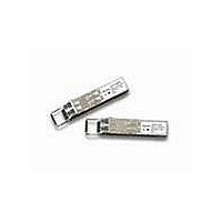
Fiber Optic Transmitters, Receivers, Transceivers DUAL SPEC SFF LC SFP 1.25/1.063
Manufacturer
Avago Technologies US Inc.
Datasheet
1.HFCT-5701LP.pdf
(12 pages)
Specifications of HFCT-5701LP
Function
SMF Pluggable (SFP) Transceiver for GbE and Fibre Channel
Product
Transceiver
Data Rate
1.25 GBd
Wavelength
1300 nm
Maximum Rise Time
400 ps, 320 ps
Maximum Fall Time
400 ps, 320 ps
Operating Supply Voltage
3.14 V to 3.47 V
Maximum Operating Temperature
+ 85 C
Minimum Operating Temperature
- 10 C
Package / Case
SFP-20
Optical Fiber Type
TX/RX
Data Transfer Rate
1250Mbps
Optical Rise Time
0.32/0.4ns
Optical Fall Time
0.32/0.4ns
Operating Temperature Classification
Commercial
Peak Wavelength
1355nm
Package Type
SFP
Operating Supply Voltage (min)
3.14V
Operating Supply Voltage (typ)
3.3V
Operating Supply Voltage (max)
3.47V
Operating Temp Range
-10C to 85C
Mounting
Snap Fit To Panel
Pin Count
20
For Use With
Singlemode Glass
Lead Free Status / RoHS Status
Lead free / RoHS Compliant


Absolute Maximum Ratings
Absolute maximum ratings are those values beyond which functional performance is not intended, device reliability is not
implied, and damage to the device may occur.
Parameter
Relative Humidity
Input Voltage on any Pin
Recommended Operating Conditions
Typical operating conditions are those values for which functional performance and device reliability is implied.
Parameter
Case Operating Temperature
Transceiver Electrical Characteristics
Parameter
Module supply current
Power Dissipation
Power Supply Noise Rejection (peak - peak)
Inrush Current
DC Electrical Characteristics
Loss of Signal (LOS) MOD-DEF2
Control Inputs:
MOD-DEF1, 2
Data Input:
Data Ouput:
Receiver Differential Output Voltage (RD+/-)
Receiver Data Rise and Fall Times
Notes:
1. Over temperature and Beginning of Life.
2. MSA filter is required on host board 10 Hz to 1 MHz. See Figure 1 (Page 2)
3. Satisfied after 500 nanoseconds. Within 500 nanoseconds, maximum of current of 2000 mA and energy of 700 nanojoules
4. LVTTL, External 4.7 - 10 KΩ Pull-Up Resistor required
5. LVTTL, Internal 4.7 - 10 KΩ Pull-Up Resistor required for TX_Disable
6. Internally ac coupled and terminated (100 Ohm differential)
7. Internally ac coupled and load termination located at the user SerDes
Storage Temperature (non-operating)
Supply Voltage
Supply Voltage
AC Electrical Characteristics
Sense Outputs:
Transmit Fault (TX_FAULT)
Transmitter Disable (TX_DISABLE)
Transmitter Differential Input Voltage (TD+/-)
8
I
P
PSNR
Symbol
T
V
Symbol
V
V
V
V
V
V
T
CC
C
DISS
rf
CC
OH
OL
IH
IL
I
O
Symbol
RH
T
V
V
S
CC
I
Minimum
-10
3.14
Minimum
2.0
2.0
500
370
Minimum
-40
5
-0.5
-0.5
3.3
200
660
100
Typical
Typical
Maximum
+85
85
3.63
V
CC
Maximum
+85
Maximum
240
762.3
0.8
0.8
2000
1600
3.47
30
VccT, R+0.3 V
Vcc
400
Unit
° C
%
V
V
Unit
° C
Unit
mA
mW
mV
mA
mV
mV
ps
V
V
V
V
Notes
1
1
Notes
Notes
2
3
4
4, 5
6
7
Related parts for HFCT-5701LP
Image
Part Number
Description
Manufacturer
Datasheet
Request
R

Part Number:
Description:
TXRX SMF XFP 10BGE 2KM OC-192
Manufacturer:
Avago Technologies US Inc.
Datasheet:

Part Number:
Description:
Fiber Optic Transmitters, Receivers, Transceivers OC3 SFP IR -10 to +8 5 non-DMI
Manufacturer:
Avago Technologies US Inc.
Datasheet:

Part Number:
Description:
Fiber Optics, Transceiver Module
Manufacturer:
Avago Technologies US Inc.
Part Number:
Description:
Fiber Optic Transmitters, Receivers, Transceivers SFP OC12 IR Standard Delatch
Manufacturer:
Avago Technologies US Inc.

Part Number:
Description:
Manufacturer:
Avago Technologies
Datasheet:

Part Number:
Description:
155 Mb/s Single Mode Laser Transceiver For Atm, Sonet OC-3/SDH STM-1 (L1.1)
Manufacturer:
Agilent Technologies, Inc.
Datasheet:
Part Number:
Description:
Fiber Optics, Evaluation Kit
Manufacturer:
Avago Technologies US Inc.
Datasheet:
Part Number:
Description:
Fiber Optics, Evaluation Kit
Manufacturer:
Avago Technologies US Inc.
Datasheet:
Part Number:
Description:
Fiber Optics, Evaluation Kit
Manufacturer:
Avago Technologies US Inc.
Datasheet:

Part Number:
Description:
Agilent HFCT-5215B/D 155 Mb/s Single Mode Laser Transceiver
Manufacturer:
Hewlett-Packard
Datasheet:

Part Number:
Description:
OPTOCOUPLER GATE DRV 2A 16-SOIC
Manufacturer:
Avago Technologies US Inc.
Datasheet:
Part Number:
Description:
OPTOCOUPLER 2CH 2.5A 16-SOIC
Manufacturer:
Avago Technologies US Inc.
Datasheet:

Part Number:
Description:
OPTOCOUPLER GATE DRV 0.4A 16SOIC
Manufacturer:
Avago Technologies US Inc.
Datasheet:

Part Number:
Description:
OPTOCOUPLER 2.0A 250KHZ 8-DIP
Manufacturer:
Avago Technologies US Inc.
Datasheet:

Part Number:
Description:
OPTOCOUPLER 2.0A 250KHZ GW 8-SMD
Manufacturer:
Avago Technologies US Inc.
Datasheet: