ACFM-7101-TR1G Avago Technologies US Inc., ACFM-7101-TR1G Datasheet - Page 5
ACFM-7101-TR1G
Manufacturer Part Number
ACFM-7101-TR1G
Description
Fiber Optic Transmitters, Receivers, Transceivers 5x8mm Filter Module Quintplexer
Manufacturer
Avago Technologies US Inc.
Series
-r
Datasheet
1.ACFM-7101-BLKG.pdf
(17 pages)
Specifications of ACFM-7101-TR1G
Function
Single antenna connection for PCS duplexer, cellular duplexer and GPS filter
Frequency Bands (low / High)
824MHz ~ 894MHz / 1.85GHz ~ 1.99GHz
Low Band Attenuation (min / Max Db)
55.00dB / -
High Band Attenuation (min / Max Db)
30.00dB / -
Return Loss (low Band / High Band)
12dB / 12dB
Mounting Type
Surface Mount
Package / Case
6-SMD, No Lead
Lead Free Status / RoHS Status
Lead free / RoHS Compliant
Available stocks
Company
Part Number
Manufacturer
Quantity
Price
Company:

Part Number:
ACFM-7101-TR1G
Manufacturer:
TOSHIBA
Quantity:
16


Absolute Maximum Ratings
Maximum Recommended Operating Conditions
Characterization
A test circuit similar to that shown in Figure 1 was used to
measure typical device performance. This circuit is designed
to interface with Air Coplanar (ACP), Ground-Signal-Ground
(GSG) RF probes of the type commonly used to test
semiconductor wafers.
Figure 1. ACP Probe Test Circuit.
The test circuit is a 17.7 x 17.7 mm PCB with a well-
grounded pad to which the device under test (DUT) is
solder-mounted.
Notes:
1. Operation in excess of any one of these conditions may result in permanent damage to the device.
2. The device will function over the recommended range without degradation in reliability or permanent change in performance, but is
3. T
Storage temperature
Maximum RF Input Power to Tx Ports
Operating temperature, Tc
Operating temperature, Tc
not guaranteed to meet electrical specifications.
C
is defined as case temperature, the temperature of the underside of the quintplexer where it makes contact with the circuit board.
[1]
[3]
[3]
Parameter
Parameter
, Tx Power 29 dBm
, Tx Power 30 dBm
[2]
Short lengths of 50-ohm microstripline connect the DUT to
ACP probe patterns on the board.
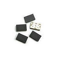
A test circuit with a ACFM-7101 mounted in place is shown
in Figure 2. S-parameters are then measured using a
network analyzer and calibrated ACP probe set.
Figure 2. Test Circuit with ACFM-7101 Quintplexer.
Phase data for s-parameters measured with ACP probe
circuits are adjusted to place the reference plane at the edge
of the quintplexer.
dBm
Unit
Unit
°C
°C
°C
–65 to +125
–40 to +100
–40 to +85
Value
Value
+33
Page 5 of 17
Related parts for ACFM-7101-TR1G
Image
Part Number
Description
Manufacturer
Datasheet
Request
R

Part Number:
Description:
Fiber Optic Transmitters, Receivers, Transceivers 5x8mm Filter Module Quintplexer
Manufacturer:
Avago Technologies US Inc.
Datasheet:
Part Number:
Description:
Fiber Optic Transmitters, Receivers, Transceivers 5x8mm Filter Module Quintplexer
Manufacturer:
Avago Technologies US Inc.
Datasheet:
Part Number:
Description:
Fiber Optic Transmitters, Receivers, Transceivers 5x8mm Filter Module Quintplexer
Manufacturer:
Avago Technologies US Inc.
Datasheet:

Part Number:
Description:
OPTOCOUPLER GATE DRV 2A 16-SOIC
Manufacturer:
Avago Technologies US Inc.
Datasheet:
Part Number:
Description:
OPTOCOUPLER 2CH 2.5A 16-SOIC
Manufacturer:
Avago Technologies US Inc.
Datasheet:

Part Number:
Description:
OPTOCOUPLER GATE DRV 0.4A 16SOIC
Manufacturer:
Avago Technologies US Inc.
Datasheet:

Part Number:
Description:
OPTOCOUPLER 2.0A 250KHZ 8-DIP
Manufacturer:
Avago Technologies US Inc.
Datasheet:

Part Number:
Description:
OPTOCOUPLER 2.0A 250KHZ GW 8-SMD
Manufacturer:
Avago Technologies US Inc.
Datasheet:

Part Number:
Description:
OPTOCOUPLER 2CH 15MBD 3.3V 8SOIC
Manufacturer:
Avago Technologies US Inc.
Datasheet:
Part Number:
Description:
OPTOCOUPLER DARL-OUT 8-DIP
Manufacturer:
Avago Technologies US Inc.
Datasheet:
Part Number:
Description:
OPTOCOUPLER IGBT DRIVE 0.4A 8DIP
Manufacturer:
Avago Technologies US Inc.
Datasheet:
Part Number:
Description:
OPTOCOUPLER DARL-OUT 8-DIP
Manufacturer:
Avago Technologies US Inc.
Datasheet:

Part Number:
Description:
OPTOCOUPLER 1CH 1MBS 8-SMD GW
Manufacturer:
Avago Technologies US Inc.
Datasheet:
Part Number:
Description:
OPTOCOUPLER GATE DRIVER 8-DIP
Manufacturer:
Avago Technologies US Inc.
Datasheet:

Part Number:
Description:
OPTOCOUPLER GATE DRIVER 8-SMD
Manufacturer:
Avago Technologies US Inc.
Datasheet: