TFBS6711-TR3 Vishay, TFBS6711-TR3 Datasheet - Page 4
TFBS6711-TR3
Manufacturer Part Number
TFBS6711-TR3
Description
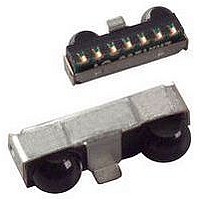
Infrared Transceivers FIR 4Mbit/s 2.4-3.6V Op Voltage
Manufacturer
Vishay
Datasheet
1.TFBS6711-TR3.pdf
(12 pages)
Specifications of TFBS6711-TR3
Wavelength
900 nm
Continual Data Transmission
4 Mbit/s
Transmission Distance
50 cm
Radiant Intensity
115 mW/sr
Half Intensity Angle Degrees
48 deg
Pulse Width
1.8 us
Maximum Rise Time
50 ns, 40 ns
Maximum Fall Time
50 ns, 40 ns
Led Supply Voltage
- 0.5 V to 6.5 V
Operating Voltage
2.4 V to 3.6 V
Maximum Operating Temperature
+ 85 C
Minimum Operating Temperature
- 25 C
Data Rate Max
4Mbps
Data Transmission Distance
50cm
Peak Wavelength
900nm
Supply Current
1.9mA
Supply Voltage Range
2.4V To 3.6V
Operating Temperature Range
-25°C To +85°C
Power Dissipation Pd
500mW
Lead Free Status / RoHS Status
Lead free / RoHS Compliant


TFBS6711
Vishay Semiconductors
Notes
(1)
(2)
www.vishay.com
4
ELECTRICAL CHARACTERISTICS
PARAMETERS
TRANSCEIVER
Supply voltage
Dynamic supply current
Shutdown supply current
Shutdown supply current
Operating temperature range
Output voltage low
Output voltage high
Internal RXD pull-up
Input voltage low (TXD, SD)
Input voltage high (TXD, SD)
Input leakage current (TXD, SD)
Input capacitance (TXD, SD)
OPTOELECTRONIC CHARACTERISTICS
PARAMETER
RECEIVER
Minimum irradiance E
angular range
Minimum irradiance E
angular range MIR mode
Minimum irradiance E
angular range FIR mode
Maximum irradiance E
angular range
No detection receiver input
irradiance (fluorescent light
noise suppression)
Rise time of output signal
Fall time of output signal
RXD pulse width of output
signal, 50 %, SIR mode
RXD pulse width of output
signal, 50 %, MIR mode
RXD pulse width of output
signal, 50 %, FIR mode
T
testing.
The typical threshold level is 0.5 x V
operating/shutdown current.
amb
= 25 °C, V
(3)
(4)
CC
= 2.4 V to 3.6 V unless otherwise noted. Typical values are for design aid only, not guaranteed nor subject to production
e
e
e
e
in
in
in
in
irdasupportAM@vishay.com, irdasupportAP@vishay.com,
For technical questions within your region, please contact one of the following:
(2)
λ = 850 nm to 900 nm, V
λ = 850 nm to 900 nm, V
λ = 850 nm to 900 nm, V
sensitive, detector is disabled in
P
T = 25 °C, not ambient light
T = 85 °C, not ambient light
90 % to 10 %, C
SD = low, MIR/FIR mode
10 % to 90 %, C
Wopt
CC
P
9.6 kbit/s to 115.2 kbit/s
Low Profile Fast Infrared Transceiver (FIR, 4 Mbit/s)
1.4 µs < P
λ = 850 nm to 900 nm
TEST CONDITIONS
Wopt
SD = low, SIR mode
TEST CONDITIONS
Input pulse length
Input pulse length
Input pulse length
(V
shutdown mode
= 217 ns, 1.152 Mbit/s
C
C
I
OH
CC
1.152 Mbit/s
= 125 ns, 4 Mbit/s
LOAD
LOAD
I
SD = high
SD = high
OL
sensitive
4 Mbit/s
= - 250 µA
= 3 V. It is recommended to use the specified min./max. values to avoid increased
= 1 mA
(1)
Wopt
= 15 pF
= 15 pF
In transmit mode, add additional 85 mA (typ.) for IRED current.
L
L
< 25 µs
= 15 pF
= 15 pF
CC
CC
CC
(1)
Add RXD output current depending on RXD load.
= 2.4 V
= 2.4 V
= 2.4 V
for IrDA
SYMBOL
®
R
V
V
V
I
V
I
I
I
I
V
T
ICH
RXD
C
CC
CC
SD
SD
CC
OH
Receive mode only.
OL
Applications
IH
IL
SYMBOL
A
I
t
t
r (RXD)
f (RXD)
t
t
t
E
E
E
E
E
PW
PW
PW
e
e
e
e
e
irdasupportEU@vishay.com
0.9 x V
V
CC
MIN.
- 0.5
- 25
400
2.4
- 1
- 0.5
CC
MIN.
(0.4)
110
110
1.4
10
10
4
TYP.
0.05
500
1.7
1.9
(500)
TYP.
(10)
(12)
100
120
250
1.8
(5)
50
5
Document Number: 84676
V
CC
MAX.
+ 85
3.6
3.3
600
0.5
+ 1
0.4
3
1
5
5
MAX.
+ 0.5
(20)
200
270
140
2.6
Rev. 1.7, 17-Sep-09
80
(8)
50
50
(mW/cm
(µW/cm
(µW/cm
(µW/cm
(µW/cm
mW/m
mW/m
mW/m
mW/m
kW/m
UNIT
UNIT
mA
mA
kΩ
µA
µA
°C
µA
pF
V
V
V
V
V
ns
ns
µs
ns
ns
2
2
2
2
2
2
2
2
2
2
)
)
)
)
)
Related parts for TFBS6711-TR3
Image
Part Number
Description
Manufacturer
Datasheet
Request
R

Part Number:
Description:
IRDA FIR TRANSCEIVER 1,9MM-e4
Manufacturer:
Vishay
Datasheet:

Part Number:
Description:
IRDA TRANSCEIVER FIR TRANSCEIVER 1
Manufacturer:
Vishay
Datasheet:
Part Number:
Description:
Low Profile Fast Infrared Transceiver Fir, 4 Mbit/s For Irda Applications
Manufacturer:
Vishay
Datasheet:
Part Number:
Description:
357-036-542-201 CARDEDGE 36POS DL .156 BLK LOPRO
Manufacturer:
Vishay
Datasheet:
Part Number:
Description:
357-036-542-201 CARDEDGE 36POS DL .156 BLK LOPRO
Manufacturer:
Vishay
Datasheet:
Part Number:
Description:
357-036-542-201 CARDEDGE 36POS DL .156 BLK LOPRO
Manufacturer:
Vishay
Datasheet:
Part Number:
Description:
357-036-542-201 CARDEDGE 36POS DL .156 BLK LOPRO
Manufacturer:
Vishay
Datasheet:
Part Number:
Description:
357-036-542-201 CARDEDGE 36POS DL .156 BLK LOPRO
Manufacturer:
Vishay
Datasheet:
Part Number:
Description:
357-036-542-201 CARDEDGE 36POS DL .156 BLK LOPRO
Manufacturer:
Vishay
Datasheet:
Part Number:
Description:
357-036-542-201 CARDEDGE 36POS DL .156 BLK LOPRO
Manufacturer:
Vishay
Datasheet:
Part Number:
Description:
357-036-542-201 CARDEDGE 36POS DL .156 BLK LOPRO
Manufacturer:
Vishay
Datasheet:
Part Number:
Description:
357-036-542-201 CARDEDGE 36POS DL .156 BLK LOPRO
Manufacturer:
Vishay
Datasheet:
Part Number:
Description:
357-036-542-201 CARDEDGE 36POS DL .156 BLK LOPRO
Manufacturer:
Vishay
Datasheet:
Part Number:
Description:
357-036-542-201 CARDEDGE 36POS DL .156 BLK LOPRO
Manufacturer:
Vishay
Datasheet:
Part Number:
Description:
357-036-542-201 CARDEDGE 36POS DL .156 BLK LOPRO
Manufacturer:
Vishay
Datasheet: