TFBS6711-TR3 Vishay, TFBS6711-TR3 Datasheet - Page 7
TFBS6711-TR3
Manufacturer Part Number
TFBS6711-TR3
Description
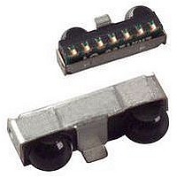
Infrared Transceivers FIR 4Mbit/s 2.4-3.6V Op Voltage
Manufacturer
Vishay
Datasheet
1.TFBS6711-TR3.pdf
(12 pages)
Specifications of TFBS6711-TR3
Wavelength
900 nm
Continual Data Transmission
4 Mbit/s
Transmission Distance
50 cm
Radiant Intensity
115 mW/sr
Half Intensity Angle Degrees
48 deg
Pulse Width
1.8 us
Maximum Rise Time
50 ns, 40 ns
Maximum Fall Time
50 ns, 40 ns
Led Supply Voltage
- 0.5 V to 6.5 V
Operating Voltage
2.4 V to 3.6 V
Maximum Operating Temperature
+ 85 C
Minimum Operating Temperature
- 25 C
Data Rate Max
4Mbps
Data Transmission Distance
50cm
Peak Wavelength
900nm
Supply Current
1.9mA
Supply Voltage Range
2.4V To 3.6V
Operating Temperature Range
-25°C To +85°C
Power Dissipation Pd
500mW
Lead Free Status / RoHS Status
Lead free / RoHS Compliant


SETTING
MODE (2.4 kbit/s to 115.2 kbit/s)
1. Set SD input to logic “high”.
2. Set TXD input to logic “low”. Wait t
3. Set SD to logic “low” (this negative edge latches state of
4. TXD must be held for t
TXD is now enabled as normal TXD input for the lower
bandwidth mode.
RECOMMENDED SOLDER PROFILES
Solder Profile for Sn/Pb Soldering
Lead (Pb)-free, Recommended Solder Profile
The TFBS6711 is a lead (Pb)-free transceiver and qualified
for lead (Pb)-free processing. For lead (Pb)-free solder paste
like Sn
profiles: Ramp-Soak-Spike (RSS) and Ramp-To-Spike
(RTS). The Ramp-Soak-Spike profile was developed
primarily for reflow ovens heated by infrared radiation. With
widespread use of forced convection reflow ovens the
Ramp-To-Spike profile is used increasingly. Shown in
figure 5 and 6 are Vishay’s recommended profiles for use
with the TFBS6711 transceivers. For more details please
refer to the application note “SMD Assembly Instructions”.
Wave Soldering
For TFDUxxxx and TFBSxxxx transceiver devices wave
soldering is not recommended.
Document Number: 84676
Rev. 1.7, 17-Sep-09
TRUTH TABLE
19431
TXD, which determines speed setting).
260
240
220
200
180
160
140
120
100
80
60
40
20
Fig. 5 - Recommended Solder Profile for Sn/Pb Soldering
0
0
High
(3.0-4.0)
Low
Low
Low
Low
Low
SD
2 °C/s to 4 °C/s
50
Ag
TO THE
(0.5-0.9)
Low Profile Fast Infrared Transceiver (FIR, 4 Mbit/s)
100
High > 80 µs
Cu, there are two standard reflow
160 °C max.
240 °C max.
120 s to 180 s
irdasupportAM@vishay.com, irdasupportAP@vishay.com,
h
High
TXD
Low
Low
Low
150
≥ 200 ns.
x
For technical questions within your region, please contact one of the following:
Time (s)
LOWER BANDWIDTH
2 °C/s to 4 °C/s
200
INPUTS
s
≥ 200 ns.
for IrDA
10 s max. at 230 °C
250
90 s max.
< max. irradiance E
> max. irradiance E
> min. irradiance E
INPUT IRRADIANCE mW/m
300
®
Applications
350
< 4
x
x
x
e
e
e
in angular range
in angular range
in angular range
Manual Soldering
Manual soldering is the standard method for lab use.
However,
recommended because the risk of damage is highly
dependent on the experience of the operator. Nevertheless,
we added a chapter to the above mentioned application note,
describing manual soldering and desoldering.
Storage
The storage and drying processes for all Vishay transceivers
(TFDUxxxx and TFBSxxx) are equivalent to MSL4.
The data for the drying procedure is given on labels on the
packing and also in the application note “Taping, Labeling,
Storage and Packing”.
19261
280
260
240
220
200
180
160
140
120
100
2
80
60
40
20
0
0
2 °C...4 °C/s
SD
TXD
Fig. 6 - Solder Profile, RSS Recommendation
irdasupportEU@vishay.com
Fig. 4 - Mode Switching Timing Diagram
for
50
Weakly pulled (500 kΩ) high
a
T ≥ 255 °C for 20 s max
T ≥ 217 °C for 50 s max
50 %
Low active (echo)
100
production
Low (active)
90 s...120 s
Vishay Semiconductors
RXD
High
High
t
s
x
150
50 %
Time/s
OUTPUTS
t
h
process
200
50 %
50 s max.
20 s
High: FIR
TFBS6711
Low: SIR
T peak = 260 °C max.
250
TRANSMITTER
it
www.vishay.com
14873
cannot
2 °C...4 °C/s
300
I
0
0
0
0
0
e
350
be
7
Related parts for TFBS6711-TR3
Image
Part Number
Description
Manufacturer
Datasheet
Request
R

Part Number:
Description:
IRDA FIR TRANSCEIVER 1,9MM-e4
Manufacturer:
Vishay
Datasheet:

Part Number:
Description:
IRDA TRANSCEIVER FIR TRANSCEIVER 1
Manufacturer:
Vishay
Datasheet:
Part Number:
Description:
Low Profile Fast Infrared Transceiver Fir, 4 Mbit/s For Irda Applications
Manufacturer:
Vishay
Datasheet:
Part Number:
Description:
357-036-542-201 CARDEDGE 36POS DL .156 BLK LOPRO
Manufacturer:
Vishay
Datasheet:
Part Number:
Description:
357-036-542-201 CARDEDGE 36POS DL .156 BLK LOPRO
Manufacturer:
Vishay
Datasheet:
Part Number:
Description:
357-036-542-201 CARDEDGE 36POS DL .156 BLK LOPRO
Manufacturer:
Vishay
Datasheet:
Part Number:
Description:
357-036-542-201 CARDEDGE 36POS DL .156 BLK LOPRO
Manufacturer:
Vishay
Datasheet:
Part Number:
Description:
357-036-542-201 CARDEDGE 36POS DL .156 BLK LOPRO
Manufacturer:
Vishay
Datasheet:
Part Number:
Description:
357-036-542-201 CARDEDGE 36POS DL .156 BLK LOPRO
Manufacturer:
Vishay
Datasheet:
Part Number:
Description:
357-036-542-201 CARDEDGE 36POS DL .156 BLK LOPRO
Manufacturer:
Vishay
Datasheet:
Part Number:
Description:
357-036-542-201 CARDEDGE 36POS DL .156 BLK LOPRO
Manufacturer:
Vishay
Datasheet:
Part Number:
Description:
357-036-542-201 CARDEDGE 36POS DL .156 BLK LOPRO
Manufacturer:
Vishay
Datasheet:
Part Number:
Description:
357-036-542-201 CARDEDGE 36POS DL .156 BLK LOPRO
Manufacturer:
Vishay
Datasheet:
Part Number:
Description:
357-036-542-201 CARDEDGE 36POS DL .156 BLK LOPRO
Manufacturer:
Vishay
Datasheet:
Part Number:
Description:
357-036-542-201 CARDEDGE 36POS DL .156 BLK LOPRO
Manufacturer:
Vishay
Datasheet: