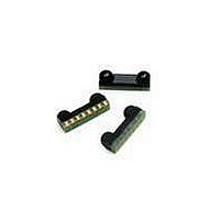
ASDL-3007-021 Avago Technologies US Inc., ASDL-3007-021 Datasheet - Page 18

ASDL-3007-021
Manufacturer Part Number
ASDL-3007-021
Description
Infrared Transceivers SIR+RC transceiver
Manufacturer
Avago Technologies US Inc.
Datasheet
1.ASDL-3007-021.pdf
(19 pages)
Specifications of ASDL-3007-021
Wavelength
885 nm, 875 nm
Continual Data Transmission
115.2 Kbit/s
Transmission Distance
50 cm
Radiant Intensity
19 mW/sr
Half Intensity Angle Degrees
30 deg to 60 deg
Pulse Width
4 us, 1.6 us
Maximum Rise Time
60 ns, 600 ns
Maximum Fall Time
60 ns, 600 ns
Led Supply Voltage
5.5 V
Maximum Forward Current
32 mA
Operating Voltage
2.4 V to 3.6 V
Maximum Operating Temperature
+ 85 C
Minimum Operating Temperature
- 25 C
Dimensions
7 mm x 2.8 mm x 1.6 mm
Lead Free Status / RoHS Status
Lead free / RoHS Compliant
Appendix D: Window Design for ASDL-3007
Window Dimension
To ensure IrDA compliance, some constraints on the
height and width of the window exist. The minimum
dimensions ensure that the IrDA cones angles are met
without vignetting. The maximum dimensions minimize
the effects of stray light. The minimum size corresponds
to a cone angle of 300 and the maximum size corre-
sponds to a cone angle of 600.
Figure D1. Window Design for ASDL-3007
In figure D1, X is the width of the window, Y is the height
of the window and Z is the distance from the ASDL-3007
to the back of the window. The distance from the center
of the LED lens to the center of the photodiode lens, K, is
5.1mm. The equations for computing the window dimen-
sions are as follows:
The above equations assume that the thickness of the
window is negligible compared to the distance of the
module from the back of the window (Z). If they are com-
parable, Z’ replaces Z in the above equation. Z’ is defined
as
where ‘t’ is the thickness of the window and ‘n’ is the re-
fractive index of the window material.
The depth of the LED image inside the ASDL-3007, D, is
4.32mm. ‘A’ is the required half angle for viewing. For IrDA
compliance, the minimum is 150 and the maximum is
300. Assuming the thickness of the window to be neg-
ligible, the equations result in the following table and
figures:
18
IR Transparent Window
OPAQUE MATERIAL
Y
X = K + 2*(Z+D)*tanA
Y = 2*(Z+D)*tanA
Z’=Z+t/n
Z
D
A
IR Transparent Window
K
X
OPAQUE MATERIAL
Figure D2. Aperture Height (x) vs. Module Depth (z)
Figure D3. Aperture Height (y) vs. Module Depth (z)
The recommended minimum aperture width and height
is based on the assumption that the center of the window
and the center of the module are the same. It is recom-
mended that the tolerance for assembly be considered
as well. The minimum window size which will take into
acount of the assembly tolerance is defined as:
X (min + assembly tolerance) = Xmin + 2*(assembly
tolerance) (Dimensions are in mm)
Y (min + assembly tolerance) = Ymin + 2*(assembly
tolerance) (Dimensions are in mm)
Module
25
20
15
10
(z) mm
18
16
14
12
10
Depth
5
0
8
6
4
2
0
0
0
0
1
2
4
5
6
7
8
9
1
1
10.09
11.24
12.40
1.55
14.71
15.86
17.02
18.17
19.
20.48
Max
2
2
Aperture Width
(x, mm)
3
3
Module Depth (z) mm
Module Depth (z) mm
10.09
10.6
11.17
11.70
12.24
min
7.42
7.95
8.49
9.02
9.56
4
4
5
5
10.76
11.92
1.07
14.2
15.8
6
Max
4.99
6.14
7.0
8.45
9.61
Aperture Height
6
(y, mm)
7
7
8
Ymax
Ymin
Min
2.2
2.85
.9
.92
4.46
4.99
5.5
6.07
6.60
7.14
Xmax
Xmin
8
9
9


