3-530655-3 TE Connectivity, 3-530655-3 Datasheet - Page 88
3-530655-3
Manufacturer Part Number
3-530655-3
Description
Manufacturer
TE Connectivity
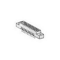
Type
Card Edger
Datasheet
1.3-530655-3.pdf
(96 pages)
Specifications of 3-530655-3
Number Of Contacts
86POS
Number Of Contact Rows
2
Body Orientation
Straight
Contact Plating
Gold Over Nickel
Contact Material
Phosphor Bronze
Termination Method
Solder
Mounting Style
Through Hole
Product Height (mm)
11.68mm
Pitch (mm)
3.96mm
Housing Material
Polyester
Housing Color
Green
Number Of Dual Positions
43
Post Type
Flow Solder Post
Mounting Ears
With
Mounting Ear Style
Without Threaded Inserts
Termination Post Length (mm [in])
3.81 [0.150]
Centerline (mm [in])
3.96 [0.156]
Row-to-row Spacing (mm [in])
5.08 [0.200]
Post Plating
Bright Tin (100)
Contact Base Material
Phosphor Bronze
Contact Plating, Mating Area, Material
Gold (30)
Underplate Material
Nickel
Rohs/elv Compliance
Not ELV/RoHS compliant
Lead Free Solder Processes
Wave solder capable to 240°C
Lead Free Status / RoHS Status
Not Compliant


88
ACTION PIN Contacts with Wiping Feature,
.100 [2.54] Centerline
Material and Finish:
Copper alloy 725, plated .000015
[0.00038] gold per MIL-G-45204 in
contact area; .000001 [0.00003] min.
gold flash per MIL-G-45204 on post
with entire contact underplated .000050
[0.00127] nickel per QQ-N-290
Contact Combs
*At least two (2) contact combs required per housing.
Note: Other sizes can be made available, consult Tyco Electronics.
Reeled Contacts
Note: Other plating combinations and thicknesses can be made available,
Catalog 1654080
Issued 7-03
www.tycoelectronics.com
[37.72]
Per Comb*
Number of
1.485
Contacts
consult Tyco Electronics.
55
Post Area
[18.92]
[18.80]
.745
.740
[2.54]
.100
Number of
Contacts
Per Reel
35,000
(Comb)
Dimensions are in inches and
millimeters unless otherwise
specified. Values in brackets
are metric equivalents.
A
Dimension
137.16
5.400
A
Technical Documents:
(pages 186, 187):
Instruction Sheet 408-2665
Related Product Data:
Performance Specifications—
page 83
ACTION PIN Contact Description
and Application Specification—
page 94
Tooling—page 95
Card Edge Connectors
(Solder Type, Board-to-Board)
Linear ZIF Connectors, .100 x .100 [2.54 x 2.54] Centerline
Contact Area
[1.14]
.045
[0.64]
.025
119196-6
Number
Part
[15.24]
.600
Sq.
Ref.
Dimensions are shown for
reference purposes only.
Specifications subject
to change.
4-119311-1
Number
at Assembly
at Assembly
Prenotched
for Breakoff
for Breakoff
Part
Prenotched
[3.05]
.120
Recommended PC Board Hole Layout and Edge Pattern,
.100 [2.54] Centerline
Mother Board Hole Layout
*For ACTION PIN post hole diameter, see page 94.
Daughter Board Edge Pattern
Connector
Connector
Dia.
Lever
Lever
Style
Style
Min.
B
USA: 1-800-522-6752
Canada: 1-905-470-4425
Mexico: 01-800-733-8926
C. America: 52-55-5-729-0425
B
Max.
A
[2.49]
.098
.100
2.54
C L
C L
Entry
Style
Side
[2.54]
Top
.100
Typ.
[2.54 (No. of Pos. –1) +4.98]
[5.08]
.200
.100 (No. of Pos. –1) +.196
.100
2.54
Min.
A
South America: 55-11-3611-1514
Hong Kong: 852-2735-1628
Japan: 81-44-844-8013
UK: 44-141-810-8967
Dimensions
.240
6.10
.240
6.10
A
[1.19]
(Solder Post Only)*
.047
(Continued)
[1.78]
Dimensions
.206
5.23
.070
Dia. Typ.
B
C
.175
4.45
.320
8.13
—
C
B
Related parts for 3-530655-3
Image
Part Number
Description
Manufacturer
Datasheet
Request
R

Part Number:
Description:
CONN HDR BRKWAY 53/54POS DUAL
Manufacturer:
Tyco Electronics
Datasheet:

Part Number:
Description:
Manufacturer:
TE Connectivity
Datasheet:
Part Number:
Description:
Manufacturer:
TE Connectivity
Datasheet:
Part Number:
Description:
Manufacturer:
TE Connectivity
Datasheet:
Part Number:
Description:
Manufacturer:
TE Connectivity
Datasheet:

Part Number:
Description:
Manufacturer:
TE Connectivity
Datasheet:

Part Number:
Description:
Conn IDC Connector F 5 POS 2.54mm IDT RA Cable Mount Loose Piece
Manufacturer:
TE Connectivity
Datasheet:

Part Number:
Description:
Conn IDC Connector F 5 POS 2.54mm IDT RA Cable Mount Loose Piece
Manufacturer:
TE Connectivity
Datasheet:

Part Number:
Description:
Conn IDC Connector F 5 POS 3.96mm IDT RA Cable Mount
Manufacturer:
TE Connectivity
Datasheet:
Part Number:
Description:
Conn IDC Connector F 5 POS 3.96mm IDT RA Cable Mount
Manufacturer:
TE Connectivity
Datasheet:

Part Number:
Description:
Conn IDC Connector F 5 POS 2.54mm IDT RA Cable Mount Loose Piece
Manufacturer:
TE Connectivity
Datasheet:

Part Number:
Description:
Manufacturer:
TE Connectivity
Datasheet:
Part Number:
Description:
05P MTA100 CONN ASSY POL 15AU
Manufacturer:
TE Connectivity
Datasheet:

Part Number:
Description:
05P MTA156 POL HDR ASSY LF
Manufacturer:
TE Connectivity
Datasheet:

Part Number:
Description:
Manufacturer:
TE Connectivity
Datasheet: