4-103325-0 TE Connectivity, 4-103325-0 Datasheet - Page 84
4-103325-0
Manufacturer Part Number
4-103325-0
Description
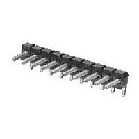
40 MODII HDR SRRA B/A .100CL
Manufacturer
TE Connectivity
Type
Unshrouded Headerr
Series
AMPMODU MOD II Seriesr
Datasheet
1.4-103325-0.pdf
(139 pages)
Specifications of 4-103325-0
Pitch (mm)
2.54mm
Gender
HDR
Number Of Contacts
40POS
Number Of Contact Rows
1
Mounting Style
Through Hole
Body Orientation
Right Angle
Contact Plating
Gold Over Nickel
Operating Temp Range
-65C to 105C
Termination Method
Solder
Current Rating (max)
3/ContactA
Contact Material
Phosphor Bronze
Housing Material
Thermoplastic
Housing Color
Black
Product Height (mm)
3.5mm
Product Length (mm)
101.19mm
Product Depth (mm)
9.39mm
Rohs Compliant
NO
Product Type
Headers - Breakaway
Pitch
2.54 mm
Number Of Positions / Contacts
40
Number Of Rows
1
Row Spacing
2.54 mm
Mounting Angle
Right
Termination Style
Solder
Current Rating
3 A
Operating Temperature Range
- 65 C to + 105 C
Mount Angle
Right Angle
Pcb Mount Retention
Without
Surface Mount Compatible
No
Board Standoff
Without
Mounting Ears
Without
Mating Connector Lock
Without
Post Size (mm [in])
0.64 [.025]
Mating Post Length (mm [in])
5.84 [0.230]
Panel Mount Retention
Without
Current Rating (a)
3
Insulation Resistance (m?)
5,000
Dielectric Withstanding Voltage (v)
750
Termination Post Length (mm [in])
3.05 [0.120]
Solder Tail Contact Plating
Tin-Lead over Nickel
Header Type
Breakaway
Number Of Positions
40
Centerline (mm [in])
2.54 [0.100]
Row-to-row Spacing (mm [in])
2.54 [0.100]
Selectively Loaded
No
Mount Type
Printed Circuit Board
Contact Plating, Mating Area, Material
Gold (15)
Contact Shape
Square
Contact Base Material
Phosphor Bronze
Ul Flammability Rating
UL 94V-0
Rohs/elv Compliance
ELV compliant, 5 of 6 Compliant
Lead Free Solder Processes
Wave solder capable to 240°C
Approved Standards
UL E28476, CSA LR7189
Operating Temperature (°c)
-65 – +105
High Temperature Housing
No
High Speed Serial Data Connector
No
Lead Free Status / RoHS Status
Not Compliant


The Reliable Plated-Through Hole Interconnect
Solderless interconnections have been popular in electrical
and electronic applications with world-wide success for
decades. They provide reliable electrical and mechanical
stability and offer applied-cost savings across the board.
For PC board applications, AMP compliant ACTION PIN
posts provide these features:
Since AMP compliant ACTION PIN posts do not have to be
soldered, problems associated with solder are eliminated,
such as:
Solderless press-fit interconnections using AMP compliant
pins are primarily integrated in, but not limited to, backplanes.
Solderless press-fit interconnections are used in racks,
especially where connectors must be fixed on the solder
side of the PC board and/or component side. In these
applications, the holes for AMP A C T I O N PIN post connectors
are covered during the soldering process and press-fitting
is performed after soldering.
Other applications for AMP ACTION PIN post
interconnections include PC boards that incorporate
components using surface mount technology (SMT). Here,
too, press-fit interconnections can be applied after
soldering, thus eliminating complications associated with
connectors suitable for surface mounting.
Catalog 1307819
Revised 6-04
www.tycoelectronics.com
Large gas-tight contact zone
High reliability due to stored energy
More resistant to damage to plated-through holes during
installation
Especially suited for multilayer PC boards
Less costly board manufacturing due to larger hole
tolerances compared to use of solid pins
Application can be made by end-user
Repairability—contact can be replaced in the same pin
location (two repairs)
Installation with no heat cycling of board
Permits mass insertion by minimizing forces needed to
insert pins as compared to solid pin press-fit application
Significant applied-cost savings in many applications
Faulty solder joints
Solder fumes; contaminants are deposited on the
contacts
Solder spots; short circuits between printed circuits
Flux residuals
Thermal strain on printed circuit boards and
components
Degasing of plated-through holes
Dimensions are in inches and
millimeters unless otherwise
specified. Values in brackets
are metric equivalents.
AMPMODU Interconnection System
AMP ACTION PIN Press-Fit Posts
Dimensions are shown for
reference purposes only.
Specifications subject
to change.
Principle of the AMP Compliant ACTION PIN Post
When an AMP compliant ACTION PIN post is inserted
into a plated-through hole, two spring members are
compressed, exerting force against the hole for a gas-tight
connection. The diameter of the hole is smaller than the
diagonal size of the pin (see cross-section illustration below).
The beam characteristics of the pin are designed so that a
plastic, as well as an elastic, deformation takes place during
insertion. The two spring members compress to different
degrees to accommodate hole tolerances. The compliant
pin also reduces strain on the board. With a rigid pin, the
elastic strain energy is stored entirely in the board, leading
to damage of the plated-through holes. With the AMP
compliant ACTION PIN post, the residual force of the
elastic deformation maintains stored energy to produce a
tight contact zone between the pin and the plated-through
hole. This maintains long-term electrical and mechanical
reliability of the interconnection.
Cross-Section Area of AMPACTIONPIN Press-Fit Post in Printed
Circuit Board Holes
USA: 1-800-522-6752
Canada: 1-905-470-4425
Mexico: 01-800-733-8926
C. America: 52-55-5-729-0425
.037 [0.94]
Minimum
Hole Dia.
South America: 55-11-3611-1514
Hong Kong: 852-2735-1628
Japan: 81-44-844-8013
UK: 44-141-810-8967
.043 [1.09]
Maximum
Hole Dia.
167
5
Related parts for 4-103325-0
Image
Part Number
Description
Manufacturer
Datasheet
Request
R

Part Number:
Description:
Conn IDC Connector F 10 POS 2.54mm IDT RA Cable Mount Loose Piece
Manufacturer:
TE Connectivity
Datasheet:

Part Number:
Description:
Conn IDC Connector F 10 POS 2.54mm IDT RA Cable Mount Loose Piece
Manufacturer:
TE Connectivity
Datasheet:

Part Number:
Description:
TERMINAL FEMALE DISCONNECT 6.35MM YELLOW
Manufacturer:
TE Connectivity
Datasheet:

Part Number:
Description:
TERMINAL FEMALE DISCONNECT 6.35MM YELLOW
Manufacturer:
TE Connectivity
Datasheet:

Part Number:
Description:
BOX HEADER STRAIGHT 40 WAY
Manufacturer:
TE Connectivity
Datasheet:

Part Number:
Description:
Manufacturer:
TE Connectivity
Datasheet:

Part Number:
Description:
Manufacturer:
TE Connectivity
Datasheet:

Part Number:
Description:
RES 390 OHM 1W 5% 2512
Manufacturer:
TE Connectivity
Datasheet:
Part Number:
Description:
Electromechanical Relay 3PST-NO/SPST-NC 8A 24VDC 720Ohm Through Hole
Manufacturer:
TE Connectivity
Datasheet:
Part Number:
Description:
ADF08ST04=DIP SWT,FLUSH,SMT-GW
Manufacturer:
TE Connectivity
Datasheet:

Part Number:
Description:
CRIMP PIN, SILVER, 1.5MM
Manufacturer:
TE Connectivity
Datasheet:

Part Number:
Description:
CRIMP SOCKET, 1.5MM
Manufacturer:
TE Connectivity
Datasheet:
Part Number:
Description:
Manufacturer:
TE Connectivity
Datasheet:
Part Number:
Description:
Res Thick Film 2512 3.3K Ohm 5% 1W ±200ppm/°C Molded SMD T/R
Manufacturer:
TE Connectivity
Datasheet:
Part Number:
Description:
Conn IDC Connector F 14 POS 2.54mm IDT RA Cable Mount Loose Piece
Manufacturer:
TE Connectivity
Datasheet: