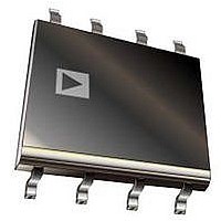
IR1155STRPBF International Rectifier, IR1155STRPBF Datasheet - Page 12

IR1155STRPBF
Manufacturer Part Number
IR1155STRPBF
Description
IC PFC ONE CYCLE CONTROL 8SOIC
Manufacturer
International Rectifier
Datasheet
1.IR1155STRPBF.pdf
(21 pages)
Specifications of IR1155STRPBF
Mode
Continuous Conduction (CCM)
Frequency - Switching
Adjustable
Current - Startup
175µA
Voltage - Supply
12 V ~ 19 V
Operating Temperature
-25°C ~ 125°C
Mounting Type
*
Package / Case
*
Startup Current
175µA
Operating Supply Current
10mA
Duty Cycle (%)
99%
Frequency
200kHz
Digital Ic Case Style
SOIC
No. Of Pins
8
Operating Temperature Range
-25°C To +125°C
Peak Reflow Compatible (260 C)
Yes
Rohs Compliant
Yes
Leaded Process Compatible
Yes
Package
8-lead SOIC
Circuit
PFC IC
Vcc Range (v)
12V-20V
Out Peak Current (a)
+/- 1.5
Switching Frequency (khz)
48 - 200
Environment
Industrial
Over-voltage Protection
Yes
Brown-out Protection
Yes
Pbf
Yes
Lead Free Status / RoHS Status
Lead free / RoHS Compliant
Other names
IR1155STRPBFTR
Available stocks
Company
Part Number
Manufacturer
Quantity
Price
Part Number:
IR1155STRPBF
Manufacturer:
IR
Quantity:
20 000
www.irf.com
Programmable Soft Start
The soft start process controls the rate of rise of
the voltage feedback loop error signal thus
providing a linear control on RMS input current
that the PFC converter will admit. The soft start
time is essentially controlled by voltage error
amplifier compensation components selected and
is therefore user programmable to some degree
based on desired loop crossover frequency.
Gate Drive Capability
The gate drive output stage of the IC is a totem
pole
capability. The gate drive is internally clamped at
13V (Typ). Gate drive buffer circuits can be easily
driven with the GATE pin of the IC to suit any
system power level.
System Protection Features
IR1155 protection features include DC bus
Overvoltage protection (OVP) via a dedicated pin,
Open-loop protection (OLP), Cycle-by-cycle peak
current limit (IPK LIMIT), Soft-current limit and
VCC under voltage lock-out (UVLO).
- Overvoltage voltage protection (OVP) feature in
IR1155 is achieved using a dedicated pin called
the OVP/EN pin. The input of OVP comparator is
connected the OVP pin. When the OVP pin
voltage exceeds V
detected and the gate drive is immediately
terminated. The gate drive is re-enabled only
after OVP pin voltage drops below V
use of a dedicated OVP/EN pin ensures that the
system
overvoltages,
(connected to the VFB pin) encounters any
failure. This ensures the best possible system
overvoltage
situations.
- Open Loop Protection (OLP) is activated
whenever the VFB pin voltage falls below V
threshold. The gate drive is then immediately
disabled, VCOMP is actively discharged and the
IC is pushed into Stand-by mode. The IC will re-
start (with soft-start) once the VFB pin voltage
exceeds V
hysteresis associated with this feature. During
start-up the IC is held in Stand-by until this pin
exceeds V
IR1155 General Description
driver
OLP
is
OLP
.
protection
with
even
protected
again. There is no voltage
OVP
1.5A
, an overvoltage situation is
if
against
the
peak
from
feed-back
current
extremes
OVP(RST)
catastrophic
. The
drive
loop
OLP
of
12
- Soft-current limit is an output voltage fold-back type
protection feature that is encountered when the RMS
current in the PFC converter exceeds a certain
magnitude that causes the internal error signal of the
voltage feedback, V
Amplitude of V
RMS input current admitted into the PFC converter.
In effect, once V
current admissible into the PFC converter has been
encountered. Any attempt to increase the RMS
current beyond this limit causes the IC to limit the
duty cycle delivered to the PFC converter, which then
has the effect of causing the DC bus voltage to droop
i.e. output voltage folds-back. The current level at
which V
the current sense resistor selected for the PFC
converter. In one way, this feature can be perceived
to offer an overpower limitation of sorts at the
conditions
performed (minimum VAC & maximum output
power).
Application Note.
-
instantaneously turns-off the gate output whenever
the ISNS pin voltage exceeds V
magnitude. The gate drive output is re-enabled only
after the magnitude of the ISNS pin voltage drops
below the V
though the IC operates based on average current
mode
decoupled from the peak current limit comparator
input, the IC is still able to provide instantaneous
response to a system overcurrent condition. This
protection feature incorporates a leading edge
blanking circuit following the comparator to improve
noise immunity.
- VCC Under Voltage Lockout protection maintains
the IC in a low current consumption, UVLO mode
during start-up if VCC pin voltage is less than the
VCC turn-on threshold, V
current consumption is less than I
typically about 200uA. Should VCC pin voltage
should drop below UVLO threshold V
after start-up, the IC is pushed back into UVLO mode
(VCOMP pin is discharged) and VCC pin has to
exceed V
Cycle-by-cycle
m
control,
CC,ON
For
saturates is closely related to the value of
ISNS(PK)
at
again to re-start operation.
m
details,
which
signal is directly proportional to the
since
m
threshold. It is clarified that even
m
peak
saturates, the maximum RMS
to saturate at its highest value.
current
please
the
CC,ON
current
© 2011 International Rectifier
averaging
. In UVLO mode the
ISNS(PK)
sense
refer
IR1155S
CC,START
limit
CC, UVLO
threshold in
to
design
circuit
protection
which is
anytime
IR1155
is
is


