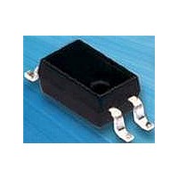
OPIA400ATU Optek, OPIA400ATU Datasheet - Page 3

OPIA400ATU
Manufacturer Part Number
OPIA400ATU
Description
Transistor Output Optocouplers 50mA 50-600CRT%
Manufacturer
Optek
Datasheet
1.OPIA402BTR.pdf
(41 pages)
Specifications of OPIA400ATU
Maximum Fall Time
18 us
Maximum Input Diode Current
50 mA
Maximum Reverse Diode Voltage
6 V
Maximum Rise Time
18 us
Output Device
Phototransistor
Output Type
DC
Configuration
1 Channel
Input Type
DC
Maximum Collector Emitter Voltage
60 V
Maximum Collector Emitter Saturation Voltage
0.2 V
Isolation Voltage
5000 Vrms
Current Transfer Ratio
600 %
Maximum Forward Diode Voltage
1.4 V
Maximum Collector Current
50 mA
Maximum Power Dissipation
200 mW
Maximum Operating Temperature
+ 100 C
Minimum Operating Temperature
- 30 C
Package / Case
PDIP-4 Gull Wing
Lead Free Status / RoHS Status
Lead free / RoHS Compliant
Optocoupler—SMD, SOP and SSOP Packages
OPIA400 through OPIA414
OPTEK Technology Inc. — 1645 Wallace Drive, Carrollton, Texas 75006
Phone: (972) 323-2200 or (800) 341-4747
Part Number
Configuration
Information
OPIA400A
OPIA401B
OPIA402B
OPIA403B
OPIA404B
OPIA405C
OPIA406C
OPIA407C
OPIA408C
OPIA409C
OPIA410A
OPIA411A
OPIA412A
OPIA413A
OPIA414B
Packaging
OPTEK reserves the right to make changes at any time in order to improve design and to supply the best product possible.
Isolation Voltage
Max. (Vrms)
Part Number Suffix:
Sensor
5,000
3,750
3,750
3,750
3,750
2,500
2,500
2,500
2,500
2,500
5,000
5,000
5,000
5,000
3,750
LED
Analog Output Devices Ordering Information
FAX: (972) 323-2396 sensors@optekinc.com www.optekinc.com
600 / 1,600 / 7,500
200 / 2,000 / -
200 / 2,000 / -
600 / - / 9,000
Min/Typ/Max
400 / 2,000 -
A = Anode
B = Base
100 / - / 600
1,000 / - / -
50 / - / 600
50 / - / 600
80 / - / 600
80 / - / 600
60 / - / 600
50 / - / 600
LED Identification—Sensor Identification
20 / - 400
70 / - / -
TU = Shipped in Tubes
CTR
Configuration: Definition of Terms
Typ. Tr / Tf (µs)
K = Cathode
C = Collector
R
L
= 100 ohms
200 / 200
200 / 200
100 / 20
60 / 53
40 / 10
80 / 72
60 / 50
4 / 3
4 / 3
5 / 4
3 / 5
3 / 5
5 / 4
2 / 3
4 / 3
4-Pin SSOP
4-Pin SSOP
4-Pin SSOP
4-Pin SSOP
4-Pin SSOP
E = Emitter
4-Pin SMD
4-Pin SMD
4-Pin SMD
4-Pin SMD
4-Pin SMD
4-Pin SOP
4-Pin SOP
4-Pin SOP
4-Pin SOP
4-Pin SOP
Package
Example: OPIA400DTU
(Dar) = Photodarlington
A K—C E (Dar)
A K—C E (Dar)
A K—C E (Dar)
A K—C E (Dar)
A K—C E (Dar)
A K—C E (Dar)
A K—C E (Dar)
Configuration
A K, K A—C E
A K, K A—C E
A K, K A—C E
A K—C E
A K—C E
A K—C E
A K—C E
A K—C E
Issue A .4
Page 3 of 41
11/08


