CRD5463PM Cirrus Logic Inc, CRD5463PM Datasheet
CRD5463PM
Specifications of CRD5463PM


Related parts for CRD5463PM


CRD5463PM Summary of contents
Page 1
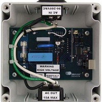
... The CRD5463PM includes two power cords, a USB cable, and a plug adaptor. When used with a PC, the CRD5463PM immediately becomes a high-precision power meter. The UART interface communication protocol, GUI, and MCU software source codes are also available from Cirrus Logic ...
Page 2
... Voltage drop and power loss in the cable connecting the CRD5463PM and the reference meter may introduce additional error. 2. The measurement bandwidth of the CS5463 is 2 kHz. At low power factor, the CRD5463PM may measure lower current and higher power factor than the reference meter if the reference meter has a measurement bandwidth greater than 2 kHz ...
Page 3
... The maximum input range of the CS5463 voltage channel is 176 mV RMS. The division ratio shall be chosen to satisfy the equation: To leave some margin, the Vout is normally set around 150 mVrms with the maximum V CRD5463PM kΩ composed of four 422 kΩ resistors to increase the total voltage rating of the voltage sensor. When V = 260 V RMS 260 V × ...
Page 4
... The power rating of the shunt should be at least twice the actual power dissipation of the shunt with the maximum continuous load current. To measure the maximum RMS and 23 A peak load current, the CRD5463PM uses a 2 mΩ, 1.5 W shunt resistor as the current sensor. ...
Page 5
... COM port through the USB connection. 3. SOFTWARE CONTROL The CRD5463PM comes with GUI software and a USB cable to link the CRD to a PC. The GUI was de- veloped with Lab Windows™/CVI™, a software development package from National Instruments Corpo- ration. The GUI software is available for download on the Cirrus Logic web site at: The software was designed to run under Windows 2000™ ...
Page 6
... Open the new folder and run the setup.exe file. 5) Follow the instructions presented by the installation wizard Run the GUI, navigate to: Start > All Programs >Cirrus Power Monitoring Reference (CRD5463PM) > CRD5463PM 4.1.2 Driver Installation Important: FTDI drivers must be installed before the GUI software is launched. Please refer to the follow- ing document for details of how to install the drivers ...
Page 7
... Connect Menu The Connect menu allows user to establish a serial communication connection with CRD5463PM. 4.3.2 System Menu The System menu allows user to operate the power monitoring and re-calibrate the CRD when necessary. DS805RD2 Figure 6. CRD5463PM GUI Connect Menu Figure 7. CRD5463PM GUI System Menu ...
Page 8
... After Connect to the CRD is selected under this menu, a sub-window will appear. Figure 9. CRD5463PM GUI Connect to CRD5463PM Window Follow the instructions on the Connect to CRD5463PM window and the The CRD is connected. message will pop up if the connection has been established correctly. Figure 10. CRD5463PM GUI Successful Connection Message Otherwise a error message will appear, indicating that the initial communication has failed ...
Page 9
... Power Monitoring Window After Monitor is selected under the System menu, the Power Monitoring window will appear. The Power Monitoring window provides the real time measurements. Figure 12. CRD5463PM GUI Power Monitoring Window 4.5.1 START and STOP Buttons To start power monitoring, click the green START button in the window. The CRD will start continuous analog-to-digital conversion, compute the power parameters every N samples, and send calculation re- sults to the GUI ...
Page 10
... The Measurement Period selection box is used to change the CS5463 CycleCount register value (N) and therefore, change the measurement period. Cycle Count (N) 8000 4000 2000 800 400 Figure 15. Power Monitoring Window, Measurement Period Menu 10 Measurement Period (Seconds 0.5 0.2 0.1 CRD5463PM Refresh Rate (Hz) 0 DS805RD2 ...
Page 11
... Irms Offset Calibration The CRD5463PM Irms offset calibration is to detect and save the residual value in the Irms register when the load is zero. This value represents the current channel noise level of the CRD. In normal power mon- itoring operation, this offset will be removed from the Irms register readings. The GUI also forces all the power measurements to be zero if the Irms register value is smaller than the offset ...
Page 12
... Gain Calibration The CRD5463PM gain calibration process is to detect and save the Vrms and Irms register values and associated true voltage and current values. In normal power monitoring operation, the GUI will use these values to convert the raw register data into true measurement results. The CRD needs gain calibration under one voltage and load condition only ...
Page 13
... SCHEMATIC DS805RD2 CRD5463PM 13 ...
Page 14
... CRD5463PM DS805RD2 ...
Page 15
... BILL OF MATERIALS DS805RD2 CRD5463PM 15 ...
Page 16
... BOARD LAYOUT 16 CRD5463PM DS805RD2 ...
Page 17
... DS805RD2 CRD5463PM 17 ...
Page 18
... CRD5463PM DS805RD2 ...
Page 19
... REVISION HISTORY Revision Date RD1 JUL 2010 RD2 OCT 2010 DS805RD2 Changes Initial Release. Updated BOM, schematic, and layer plots to rev B. CRD5463PM 19 ...
Page 20
... Cirrus Logic, Cirrus, and the Cirrus Logic logo designs are trademarks of Cirrus Logic, Inc. All other brand and product names in this document may be trademarks or service marks of their respective owners. Lab Windows and CVI are trademarks of National Instruments Corporation. Windows 2000 and Windows XP are either trademarks or registered trademarks of Microsoft Corporation. Atmel is a registered trademark or trademark of Atmel Corporation or its subsidiaries. 20 CRD5463PM DS805RD2 ...