PIC-LCD Olimex Ltd., PIC-LCD Datasheet - Page 2
PIC-LCD
Manufacturer Part Number
PIC-LCD
Description
MCU, MPU & DSP Development Tools DEV BRD FOR PIC18LF8490
Manufacturer
Olimex Ltd.
Datasheet
1.PIC-LCD.pdf
(17 pages)
Specifications of PIC-LCD
Processor To Be Evaluated
PIC18F8490
Interface Type
RS-232, I2C, SPI
Dimensions
3 in x 2.5 in
Operating Supply Voltage
9 V
Lead Free Status / RoHS Status
Lead free / RoHS Compliant
Available stocks
Company
Part Number
Manufacturer
Quantity
Price
Company:

Part Number:
PIC-LCD
Manufacturer:
Olimex Ltd.
Quantity:
135
Company:
Part Number:
PIC-LCD3310
Manufacturer:
Olimex Ltd.
Quantity:
135


INTRODUCTION:
BOARD FEATURES:
ELECTROSTATIC WARNING:
BOARD USE REQUIREMENTS:
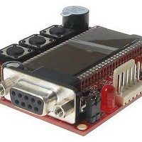
PIC-LCD is simple but powerful board which uses Microchip's PIC18F8490
microcontroller. PIC-LCD is equipped with LCD display, three user buttons,
LED, possibility for battery power supply, thermistor and buzzer. This
board is excellent for applications in monitoring (temperature measuring)
and alarm systems.
The PIC-LCD board is shipped in protective anti-static packaging. The
board must not be subject to high electrostatic potentials. General practice
for working with static sensitive devices should be applied when working
with this board.
Cables:
Hardware: Programmer/Debugger – PIC-ICD2, PIC-ICD2-POCKET, PIC-
!!!Warning!!!
MCU: PIC18F8490 with 16KB Flash memory, 768 B RAM memory, LCD
driver, 10bit ADC, PWM, SPI, I2C, EUSART, timers, comparators, up to
40 MHz operation
RS232 driver and connector
Status LED with jumper
Three user buttons
Buzzer
20 MHz crystal on socket (may be changed to any value by the user)
32768 Hz crystal on-board
On-board thermistor for temperature measurement
Extension connector for the unused PIC ports
Backup +4.5 battery connector
Single power supply: 6 VAC or 9 VDC required (must not exceed 12 VDC
or input voltage regulator will be destroyed!)
PCB: FR-4, 1.5 mm (0.062''), soldermask, silkscreen component print
Dimensions 72.6 x 64 mm (3 x 2.5")
ICSP connector for PIC-ICD2 debugger or PIC-PGx programmers
1.8 meter USB A-B cable to connect PIC-ICD2 or PIC-ICD2-
POCKET to USB host on PC. If you use PIC-PGx, you will need
RS232 cable. Other cables might be required in case of other
programming/debugging tools.
PGx or other compatible programming/debugging tool.
ICD2, PIC-ICD2-POCKET or PIC-ICD2-TINY, before connecting
the programmer to your target board, you should first connect
the programmer to your computer and open MPLAB. There,
first from menu Configure – Select Device – choose the
microcontroller you are about to program, then from menu
Programmer – Select Programmer – choose MPLAB ICD 2, wait
while MPLAB is downloading operation system, and after ICD2
is connected – check in menu Programmer – Settings – Power –
there is option – Power target circuit from MPLAB ICD 2 – this
When you want to program this microcontroller with PIC-
Related parts for PIC-LCD
Image
Part Number
Description
Manufacturer
Datasheet
Request
R

Part Number:
Description:
MCU, MPU & DSP Development Tools MPLAB 8/18/28/40P FOR PICSTART+
Manufacturer:
Olimex Ltd.

Part Number:
Description:
MCU, MPU & DSP Development Tools DEV BRD FOR 28 PIN MICRO CONT
Manufacturer:
Olimex Ltd.
Datasheet:

Part Number:
Description:
MCU, MPU & DSP Development Tools PROTOTYPE BRD FOR 40 PIN PIC
Manufacturer:
Olimex Ltd.
Datasheet:

Part Number:
Description:
MCU, MPU & DSP Development Tools PROTOTYPE BRD ICSP/ ICD ENABLED 28 PIN
Manufacturer:
Olimex Ltd.
Datasheet:

Part Number:
Description:
MCU, MPU & DSP Development Tools PROTOTYPE BRD ICSP/ ICD ENABLED 14 PIN
Manufacturer:
Olimex Ltd.
Datasheet:

Part Number:
Description:
MCU, MPU & DSP Development Tools PROTOTYPE BRD FOR 28 PIN PIC
Manufacturer:
Olimex Ltd.
Datasheet:

Part Number:
Description:
Development Boards & Kits - PIC / DSPIC MINI PROTOTYPE BRD FOR 8 PIN PIC
Manufacturer:
Olimex Ltd.

Part Number:
Description:
MCU, MPU & DSP Development Tools TCP-IP DEV BRD FOR PIC18F67J60
Manufacturer:
Olimex Ltd.
Datasheet:

Part Number:
Description:
MCU, MPU & DSP Development Tools PROTOTYPE BRD ICSP/ ICD ENABLED 40 PIN
Manufacturer:
Olimex Ltd.
Datasheet:

Part Number:
Description:
MCU, MPU & DSP Development Tools DEV BRD W/GSM MOD PIC18F97J60-I/PT
Manufacturer:
Olimex Ltd.
Datasheet:

Part Number:
Description:
Microcontroller & Microprocessor Development Tools TCP-IP DEV BRD PIC32MX460F512
Manufacturer:
Olimex Ltd.
Datasheet:

Part Number:
Description:
Microcontroller & Microprocessor Development Tools PROTOTYPE BOARD TMS320F28027
Manufacturer:
Olimex Ltd.
Datasheet:

Part Number:
Description:
Microcontroller & Microprocessor Development Tools HDR BRD FOR LPC3131
Manufacturer:
Olimex Ltd.
Datasheet:

Part Number:
Description:
Microcontroller & Microprocessor Development Tools MP3 PLYR MOD WITH VS1002
Manufacturer:
Olimex Ltd.
Datasheet:
Part Number:
Description:
Microcontroller & Microprocessor Development Tools MP3 PLYR MOD BAT WITH VS1002
Manufacturer:
Olimex Ltd.
Datasheet: