AC164130-2 Microchip Technology, AC164130-2 Datasheet - Page 13
AC164130-2
Manufacturer Part Number
AC164130-2
Description
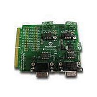
MCU, MPU & DSP Development Tools CAN/LIN PICtail Plus Daughter Board
Manufacturer
Microchip Technology
Series
PICtail™ Plusr
Datasheet
1.AC164130-2.pdf
(32 pages)
Specifications of AC164130-2
Processor To Be Evaluated
PIC18
Product
Microcontroller Modules
Main Purpose
Interface, CAN, ECAN LIN
Embedded
No
Utilized Ic / Part
MCP2021, MCP2551
Primary Attributes
2 CAN and 2 LIN Transceivers, 4 Socketed IC's
Secondary Attributes
Requires Explorer 16 Board
Lead Free Status / RoHS Status
Lead free / RoHS Compliant
Available stocks
Company
Part Number
Manufacturer
Quantity
Price
Company:

Part Number:
AC164130-2
Manufacturer:
Microchip Technology
Quantity:
135


1.2
FIGURE 1-3:
2011 Microchip Technology Inc.
LIN1
Bus
LIN2
Bus
CAN1
Bus
CAN2
Bus
FUNCTIONAL OVERVIEW
High
Low
High
Low
CAN/LIN/J2602 PICtail
The block diagram shown in Figure 1-3 illustrates the mainstream operation of the
CAN/LIN/J2602 PICtail™ (Plus) Daughter Board. The board contains two LIN signal
conditioning circuits and two CAN signal conditioning circuits. The board also enables
power to be provided by the development board it is connected to, or by an external
12V DC source.
CAN/LIN/J2602 PICtail
1.2.1
The CAN/LIN/J2602 PICtail™ (Plus) Daughter Board connects two LIN transceivers
with integrated voltage regulators to UART modules on a dsPIC33F, PIC24 or PIC18
control device on the Explorer 16 or PIC18 Explorer Board. The LIN transceiver moni-
tors the LIN bus, conditions the incoming signal and passes it to the UART module on
the control device. The LIN transceiver responds to a “Transmit Enable” from the con-
trol device by conditioning an output signal and placing it on the LIN bus.
A Power-down mode turns the transmitter and voltage regulator off, leaving only the
receiver and wake-up circuits in operation. Each LIN circuit includes a Master/Slave
jumper to accommodate a Master node on the LIN bus.
In order to use the transmit enable for the LIN2 transceiver with the PIC18 Explorer
Board and a PIC18 device, the LIN2TXE pin must be connected to 5V, or a pin on the
PIC18 device, to control it. This can be done by connecting a jumper wire on the J18
header between LIN2TXE and either the 5V supply also on the J18 header, or an avail-
able pin on either the J17 or J18 header. For more information on the J17 and J18
headers see Section 2.3 “Auxiliary Header Pinouts”.
Transceiver
Transceiver
Transceiver
Transceiver
CAN1
CAN2
LIN2
LIN1
(U2)
(U3)
(U4)
(U1)
LIN Operation
™
(Plus) DAUGHTER BOARD
Receive
Transmit Enable
Transmit
Interrupt/Wake
Receive
Transmit Enable
Transmit
Interrupt/Wake
Receive
Transmit
Receive
Transmit
™
(Plus) DAUGHTER BOARD BLOCK DIAGRAM
DEVELOPMENT BOARD
To UART Module on
dsPIC33F, PIC24 or PIC18
To ECAN Module on
dsPIC33F, PIC24 or PIC18
Introduction
DS70319B-page 13
Related parts for AC164130-2
Image
Part Number
Description
Manufacturer
Datasheet
Request
R

Part Number:
Description:
Fuses 16A 415V AC/250V DC
Manufacturer:
Apex Tool Group (Formerly Cooper Tools)

Part Number:
Description:
Manufacturer:
Microchip Technology Inc.
Datasheet:
Part Number:
Description:
Manufacturer:
Microchip Technology Inc.
Datasheet:
Part Number:
Description:
Manufacturer:
Microchip Technology Inc.
Datasheet:
Part Number:
Description:
Manufacturer:
Microchip Technology Inc.
Datasheet:
Part Number:
Description:
Manufacturer:
Microchip Technology Inc.
Datasheet:
Part Number:
Description:
Manufacturer:
Microchip Technology Inc.
Datasheet:
Part Number:
Description:
Manufacturer:
Microchip Technology Inc.
Datasheet:
Part Number:
Description:
Manufacturer:
Microchip Technology Inc.
Datasheet: