AC164130-2 Microchip Technology, AC164130-2 Datasheet - Page 18
AC164130-2
Manufacturer Part Number
AC164130-2
Description
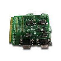
MCU, MPU & DSP Development Tools CAN/LIN PICtail Plus Daughter Board
Manufacturer
Microchip Technology
Series
PICtail™ Plusr
Datasheet
1.AC164130-2.pdf
(32 pages)
Specifications of AC164130-2
Processor To Be Evaluated
PIC18
Product
Microcontroller Modules
Main Purpose
Interface, CAN, ECAN LIN
Embedded
No
Utilized Ic / Part
MCP2021, MCP2551
Primary Attributes
2 CAN and 2 LIN Transceivers, 4 Socketed IC's
Secondary Attributes
Requires Explorer 16 Board
Lead Free Status / RoHS Status
Lead free / RoHS Compliant
Available stocks
Company
Part Number
Manufacturer
Quantity
Price
Company:

Part Number:
AC164130-2
Manufacturer:
Microchip Technology
Quantity:
135


CAN/LIN/J2602 PICtail
DS70319B-page 18
2.2.8
A pair of MCP2551 CAN transceivers (see Reference 11 and Reference 14) provide
the interface between the ECAN modules on the dsPIC33F, PIC24 or PIC18 control
device and the CAN bus. The transceiver converts the signals from the ECAN modules
on the dsPIC33F, PIC24 or PIC18 device to a pair of differential CAN bus signals.
2.2.9
Termination Jumpers (JP4, JP5) are provided to terminate the CAN bus. Jumper JP4
(see Reference 12) places a 120 ohm termination resistor across the CAN bus con-
nected to CAN1. Jumper JP5 (see Reference 16) places a 120 ohm termination
resistor across the CAN bus connected to CAN2.
2.2.10
Nine-pin D-type connectors connect the CAN/LIN/J2602 PICtail (Plus) Daughter Board
to a CAN bus. CAN1 connector P1 (see Reference 13) connects ECAN 1 module on
the dsPIC33F, PIC24 or PIC18 control device to the CAN bus via the CAN transceiver.
CAN2 connector P2 (see Reference 15) connects ECAN 2 module on the dsPIC33F or
PIC24 device and the ECAN1 module’s alternate pinout on the PIC18 device to the CAN
bus via the CAN transceiver.
For PIC18 devices, the alternate pinout of the ECAN1 module can be used on two sets
of pins chosen by the J15 and J16 jumpers. Choose the correct pinout corresponding
to the PIC18 device used. The CAN bus provides high and low differential signals.
2.2.11
For PIC18 devices, depending on which device is used and how many pins it has, the
LIN1 and LIN2 module will be available on two different sets of pins. The J4, J8, J13
and J14 jumpers are used to select between these two options (see Reference 17).
2.2.12
For PIC18 devices, depending on which device is used and how many pins it has, the
CAN 1 module’s alternate pinout chosen by its internal multiplex will be available on
two different sets of pins. The J15 and J16 jumpers are used to select between these
two options (see Reference 18).
2.2.13
PIC18 Explorer Board PICtail connector (see Reference 19) is made up of five connec-
tors that carry signals from the I/O pins of the PIC18 device on the PIC18 Explorer
Board to the CAN/LIN/J2602 PICtail (Plus) Daughter Board. This connector handles
the following signals:
• 9V, 5V and 3.3V DC input to the CAN/LIN/J2602 PICtail (Plus) Daughter Board
• Signals from the ECAN module on the PIC18 device to the CAN transceivers on
• Signals from the UART modules on the PIC18 device to the LIN transceivers on
• LIN Bus Fault Communication
the CAN/LIN/J2602 PICtail (Plus) Daughter Board
the CAN/LIN/J2602 PICtail (Plus) Daughter Board
CAN Transceivers (U3, U4)
CAN Bus Termination Jumpers (JP4, JP5)
CAN Bus Connectors (P1, P2)
Alternate LIN1 and LIN2 Module Pinout Jumpers (J4, J8, J13, J14)
Alternate CAN1 Module Alternate Pinout Jumpers (J15, J16)
PIC18 Explorer Board PICtail™ Connector (J3, J5, J6, J9, J11)
™
(Plus) Daughter Board User’s Guide
2011 Microchip Technology Inc.
Related parts for AC164130-2
Image
Part Number
Description
Manufacturer
Datasheet
Request
R

Part Number:
Description:
Fuses 16A 415V AC/250V DC
Manufacturer:
Apex Tool Group (Formerly Cooper Tools)

Part Number:
Description:
Manufacturer:
Microchip Technology Inc.
Datasheet:
Part Number:
Description:
Manufacturer:
Microchip Technology Inc.
Datasheet:
Part Number:
Description:
Manufacturer:
Microchip Technology Inc.
Datasheet:
Part Number:
Description:
Manufacturer:
Microchip Technology Inc.
Datasheet:
Part Number:
Description:
Manufacturer:
Microchip Technology Inc.
Datasheet:
Part Number:
Description:
Manufacturer:
Microchip Technology Inc.
Datasheet:
Part Number:
Description:
Manufacturer:
Microchip Technology Inc.
Datasheet:
Part Number:
Description:
Manufacturer:
Microchip Technology Inc.
Datasheet: