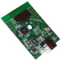
DLP-RF1-Z DLP Design Inc, DLP-RF1-Z Datasheet - Page 5

DLP-RF1-Z
Manufacturer Part Number
DLP-RF1-Z
Description
Zigbee / 802.15.4 Modules & Development Tools PC INTERFACE HOST MODULE (USB)
Manufacturer
DLP Design Inc
Datasheet
1.DLP-RF1-Z-G.pdf
(10 pages)
Specifications of DLP-RF1-Z
Wireless Frequency
2.4 GHz
Interface Type
USB
Operating Voltage
9 V
Antenna
Integral to PCB Design?No External
For Use With/related Products
MC13193, MC9S08GT60
Lead Free Status / RoHS Status
Lead free / RoHS Compliant
If a packet is received via the RF transceiver with the correct ID, then the packet is either processed by
the MC9S08GT60 or forwarded on to the host. Commands between 0xA0 and 0xBF are Command
Packets that are to be processed by the MC9S08GT60, while commands between 0xC0 and 0xDF are
Reply Packets and are forwarded on to the host.
If a packet arrives via the RF transceiver with an ID of 0 (zero), then the packet is a “broadcast” packet
intended for the system controller (the RF1/RF2 unit that is designated as system controller). ID:0
packets are always immediately forwarded on to the host.
If a packet arrives via the RF transceiver with a non-zero ID that does not match the EEPROM, then the
packet is ignored. The only exception to this is if “Return All Packets” Mode is enabled, in which case
the DLP-RF1 is monitoring packet traffic, and all unsolicited packets are returned to the serial host.
**Under this communication protocol, it is the responsibility of the host application to “Retry”
transmissions that do not produce the anticipated reply.**
Rev 1.5 (November 2005)
0xAC
0xAD
0xAA
0xAB
0xAE
0xAF
Cmd
0xA0
0xA1
0xA2
0xA3
0xA4
0xA5
0xA6
0xA7
0xA8
0xA9
0xB6
0xB7
Packet Recipient
MC9S08GT60
MC9S08GT60
MC9S08GT60
MC9S08GT60
MC9S08GT60
MC9S08GT60
MC9S08GT60
MC9S08GT60
MC9S08GT60
MC9S08GT60
MC9S08GT60
MC9S08GT60
MC9S08GT60
MC9S08GT60
MC9S08GT60
MC9S08GT60
MC9S08GT60
MC9S08GT60
Description
Ping (no data)
Set Transmit Power Level
1 Data Byte; Range: 0-15
Set Transceiver Channel
1 Data Byte; Range: 0-15
Set RF2 Baud Rate (RF2 Only)
Release immediately to Sleep
(DLP-RF2 only) (no data)
Measure energy on all channels (no data)
Return all packets received to host
(Packet Watch Mode—no data)
Return only packets with correct ID to host
(Default mode) (no data)
Read EEPROM
1 Data Byte; Address: 0-31
Write EEPROM and update checksum
2 Data Bytes; Address: 0-30; Data: 0-255
Read I/O pin, 1 Data Byte: Port: 0-7 (RF2
Only)
Set I/O pin direction, 2 Data Bytes: Port: 0-
7, Direction: 1=Out, 0=In (RF2 only)
Set/Clear I/O pin, 2 Data Bytes: Port: 0-7,
State: 0/1 (RF2 Only)
Setup A/D, 2 Data Bytes: Port: 0-6, Mode:
0=Off, 1=On (RF2 Only)
Read A/D, 1 Data Byte: Channel: 0-6 (RF2
Only)
Read VBAT (no data) (RF2 Only)
Request Board Type (DLP-RF1, RF2),
ROM and RFIC versions (no data)
Return Board ID (not available through RF
transceiver, physical connection only)
(destination ID ignored) (no data)
5
DLP-RF1/Z DLP Design, Inc.
Reply Cmd
Expected
0xCD
0xCA
0xCB
0xC0
0xC0
0xC0
0xC0
0xC0
0xC3
0xC0
0xC0
0xC4
0xC5
0xC6
0xC7
0xC8
0xC9
0xCF


