7-338069-8 TE Connectivity, 7-338069-8 Datasheet - Page 6
7-338069-8
Manufacturer Part Number
7-338069-8
Description
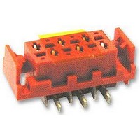
SOCKET, TOP ENTRY, SMT, 8WAY
Manufacturer
TE Connectivity
Type
FFC Connectorr
Series
Micro-MaTchr
Datasheet
1.8-215079-2.pdf
(15 pages)
Specifications of 7-338069-8
Contact Gender
F
Mounting Style
Surface Mount
Number Of Contact Rows
2
Number Of Contacts
8POS
Pitch (mm)
2.54mm
Body Orientation
Straight
Contact Resistance Max
10mOhm
Operating Temp Range
-40C to 105C
Housing Material
Polyamide 4.6
Housing Color
Red
Contact Material
Phosphor Bronze
Contact Plating
Tin Over Nickel
Termination Method
Solder
Product Height (mm)
5.3mm
Product Depth (mm)
5mm
Product Length (mm)
14.7mm
Connector Type
Board To Board
Pitch Spacing
1.27mm
No. Of Rows
1
No. Of Contacts
8
Gender
Receptacle
Contact Termination
Surface Mount Vertical
Contact
RoHS Compliant
Rohs Compliant
Yes
Product Type
Connector
Type Of Connector
Female-On-Board
Mount Angle
Vertical
Pcb Mount Style
Surface Mount
Mating Connector Lock
With
Polarization
With
Number Of Positions
8
Locking Latch
With
Centerline (mm [in])
1.27 [0.050]
Vacuum Tape
With
Contact Base Material
Phosphor Bronze
Contact Plating, Mating Area, Material
Tin
Housing Entry Style
Top
Rohs/elv Compliance
RoHS compliant, ELV compliant
Lead Free Solder Processes
Reflow solder capable to 245°C, Reflow solder capable to 260°C
Rohs/elv Compliance History
Always was RoHS compliant
Applies To
Printed Circuit Board
Packaging Method
Reel
Packaging Quantity
900
Lead Free Status / RoHS Status
Compliant
Available stocks
Company
Part Number
Manufacturer
Quantity
Price
Company:

Part Number:
7-338069-8
Manufacturer:
TE
Quantity:
20 000
Company:
Part Number:
7-338069-8
Manufacturer:
TE Connectivity AMP Connectors
Quantity:
124


.
Rev. F
R6-77 (Rev. 07-01)
3.6.1.
3.6.2.
3.6.3.
3.6.4.
3.6.5.
Para.
3.6.6.
3.6.7.
3.6.8.
Examination of product
Solderability for through hole
versions
Resistance to soldering heat
for through hole versions
Solderability for SMD
Resistance to Soldering Heat
for SMD
Insulation resistance
Voltage proof
Termination resistance
Measuring points
Termination resistance
Test description
Test description
Meets requirements of product
drawing and applicable AMP
spec. 114-19016, 114-19051 or
114-19027.
Solderbath temp 235°C.
Ageing 3-16 hrs at 155°C
Max. 5% dewetting
Solderbath temp. 265°C
Dip duration: 10 seconds
Mount connectors in a PC-Board
as intended to be applied.
Requirement: No detrimental
effects.
Appearance of the specimen shall
be inspected after the test with
10x magnification of any damage
such as pinholes, void or rough
surface.
3 cycles of 260°C peak reflow
soldering simulation curve.
Test severity shall not include
moisture soak.
Requirement: No detrimental
effects.
Test voltage 100V DC- or AC-
peak. Duration: 1 minute.
Requirement: 1000 MΩ min.
Test voltage: 500 VAC.
Duration: 1 minute
Requirement: No break-down
or flash-over
Maximum open voltage 20
Millivolts. Maximum current 100
Milliampers. Termination
resistance consists of bulk cable +
bulk connectors and contact
resistance. Requirement: 10
Milliohms max. (excluding bulk
cable)
E L E C T R I C A L
Performance Requirements
Performance Requirements
VISUAL
or Severity
or Severity
Visual,
functional
inspection plan. In acc. with
IEC 512-2 test 1a.
Magnification 10 x.
In acc. with IEC 68-2-20
Test Ta
In acc. with:
Tyco Test Spec 109-202
Method § 4.3.B.
Provisional standards of EIA
of
( Test methods of soldering or
surface
Para 2.4.2. ( Reflow soldering
method )
In acc. with:
Tyco Test Spec 109-201
Reflow curve § 3.4.B.2.
In acc. with IEC 512-2 test 3a.
In acc. with IEC 512-2 test 4a.
In acc. with IEC 512-2 test 2a.
Under dry circuit conditions.
All contacts measured.
JAPAN.
Procedures
mounting
dimensional
Procedures
per
RCX-0102/101
108-19052
Page 6 of 15
applicable
devices)
and
Related parts for 7-338069-8
Image
Part Number
Description
Manufacturer
Datasheet
Request
R

Part Number:
Description:
33-012A=DISC,RESET,W58,ABS,,,.
Manufacturer:
Tyco Electronics
Datasheet:

Part Number:
Description:
SQP15 33R 5% WIRE
Manufacturer:
Tyco Electronics
Datasheet:

Part Number:
Description:
Manufacturer:
Huber + Suhner AG
Datasheet:
Part Number:
Description:
7 A LOW DROPOUT POSITIVE REGULATORS
Manufacturer:
MICROSEMI [Microsemi Corporation]
Datasheet:

Part Number:
Description:
Manufacturer:
TE Connectivity
Datasheet:
Part Number:
Description:
Manufacturer:
TE Connectivity
Datasheet:

Part Number:
Description:
Manufacturer:
TE Connectivity
Datasheet:
Part Number:
Description:
Manufacturer:
TE Connectivity
Datasheet:

Part Number:
Description:
Manufacturer:
TE Connectivity
Datasheet:

Part Number:
Description:
Manufacturer:
TE Connectivity
Datasheet:

Part Number:
Description:
RT314A03
Manufacturer:
TE Connectivity
Datasheet:
Part Number:
Description:
Manufacturer:
TE Connectivity
Datasheet:

Part Number:
Description:
CONN SEC II 6 POS 100C/L
Manufacturer:
TE Connectivity
Datasheet: