2-794632-0 TE Connectivity, 2-794632-0 Datasheet

Power to the Board HDR VERT 20P 30 AU DUAL

2-794632-0

Manufacturer Part Number
2-794632-0
Description
Power to the Board HDR VERT 20P 30 AU DUAL
Manufacturer
TE Connectivity
Type
Powerr
Datasheets

Specifications of 2-794632-0

Gender
HDR
Body Orientation
Straight
Housing Material
Nylon
Number Of Contacts
20POS
Number Of Ports
1Port
Number Of Terminals
20
Current Rating (max)
5/ContactA
Pitch (mm)
3mm
Contact Material
Brass
Operating Temp Range
-40C to 105C
Voltage Rating Max
250VAC
Mounting Style
Through Hole
Termination Method
Solder
Contact Plating
Gold
Product Height (mm)
9.24mm
Product Depth (mm)
8.67mm
Product Length (mm)
34mm
Product Type
Plug Housings
Number Of Positions / Contacts
20
Connector Type
Header
Mount Angle
Vertical
Mount
Printed Circuit Board
Pcb Mount Alignment
Without
Product Line
Micro MATE-N-LOK
Mating Retention Type
Latching
Voltage (vac)
250
Current Rating (a)
5
Termination Post Length (mm [in])
3.18 [0.125]
Solder Tail Contact Plating
Tin-Lead
Number Of Positions
20
Number Of Rows
2
Row-to-row Spacing (mm [in])
3.00 [0.118]
Centerline (mm [in])
3.00 [0.118]
Pcb Mount Retention Type
Compliant Posts
Mating Retention
With
Contact Type
Pin
Contact Termination Type
Through Hole
Contact Layout
Double-Row
Contact Plating, Mating Area, Material
Gold (30)
Contact Base Material
Brass
Connector Style
Plug
Housing Color
Black
Ul Flammability Rating
UL 94V-0
Rohs/elv Compliance
Not ELV/RoHS compliant
Lead Free Solder Processes
Not suitable for lead free processing
Applies To
Printed Circuit Board
Pcb Thickness, Recommended (mm [in])
1.57 [0.062]
Lead Free Status / RoHS Status
Not Compliant
1.
1.1.
1.2.
1.3.
2.
2.1.
2.2.
3.
3.1.
3.2.
©2011 Tyco Electronics Corporation,
a TE Connectivity Ltd. Company
All Rights Reserved
TE logo is a trademark.
SCOPE
Content
This specification covers performance, tests and quality requirements for the 3 mm Micro MATE-N-
LOK* connector family. This connector family has wire-to-board and wire-to-wire configurations. The
connectors are available in 2 to 24 positions in a double row configuration, and 2 to 12 positions in a
single row configuration, with both configurations using 20 to 30 AWG wire.
Qualification
When tests are performed on the subject product line, procedures specified in Figure 1 shall be used.
All inspections shall be performed using the applicable inspection plan and product drawing.
Qualification Test Results
Successful qualification testing on the subject product line was completed on 16Jan02. The
Qualification Test Report number for this testing is 501-526. This documentation is on file at and
available from Engineering Practices and Standards (EPS).
APPLICABLE DOCUMENTS
The following documents form a part of this specification to the extent specified herein. Unless
otherwise specified, the latest edition of the document applies. In the event of conflict between the
requirements of this specification and the product drawing, the product drawing shall take precedence.
In the event of conflict between the requirements of this specification and the referenced documents,
this specification shall take precedence.
TE Connectivity (TE) Documents
!
!
!
Commercial Standard
EIA-364: Electrical Connector/Socket Test Procedures Including Environmental Classifications
REQUIREMENTS
Design and Construction
Product shall be of the design, construction and physical dimensions specified on the applicable product
drawing.
Materials
Materials used in the construction of this product shall be as specified on the applicable product
drawing.
109 Series: Test Specifications as indicated in Figure 1
109-197: Test Specification (TE Test Specifications vs EIA and IEC Test Methods)
501-526: Qualification Test Report (3 mm Micro MATE-N-LOK* Connector)
| Indicates change
*Trademark
Product
Specification
3 mm Micro MATE-N-LOK* Connector
For latest revision, visit our website at www.te.com/documents.
For Regional Customer Service, visit our website at www.te.com
Other products, logos, and company names might be trademarks of their respective owners.
108-1836
11Mar11 Rev D
1 of 7
LOC B

Related parts for 2-794632-0

2-794632-0 Summary of contents

Page 1

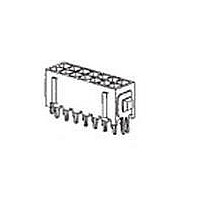
... This specification covers performance, tests and quality requirements for the 3 mm Micro MATE-N- LOK* connector family. This connector family has wire-to-board and wire-to-wire configurations. The connectors are available positions in a double row configuration, and positions in a single row configuration, with both configurations using AWG wire. ...

Page 2

... Ratings ! Voltage: 250 volts Current: See Figure 1 for applicable current carrying capability ! Temperature: -40 to 105° C 3.4. Performance and Test Description Product is designed to meet the electrical, mechanical and environmental performance requirements specified in Figure 1. Unless otherwise specified, all tests shall be performed at ambient environmental conditions per EIA-364 ...

Page 3

... EIA-364-52, Category 3 For thru-hole. EIA-638 for surface mount. Subject contacts to solderability. EIA-364-8. Determine crimp tensile at a maximum rate of 25 ± [.98 ± .24 in] per minute. EIA-364-28, Test Condition VII, Condition D. Subject mated specimens to 3.10 G's rms between 20-500 Hz. 15 minutes in each of 3 mutually perpendicular planes ...

Page 4

... EIA-364-32, Test Condition VIII. Subject specimens to 5 cycles between -40 and 105° C. EIA-364-31, Method III. Subject specimens to 10 cycles (10 days) between 25 and 65° 100% RH. EIA-364-17, Method A, Test Condition 4, Test Time Condition C. Subject mated specimens to 105° C for 500 hours. ...

Page 5

... Test omitted when testing wire-to-wire connectors. (d) The fourth test in this sequence will be either humidity/temperature cycling for tin plated specimens or mixed flowing gas for gold plated specimens. Precondition specimens with 10 cycles of durability. Rev D Test Group ( Test Sequence ( 3,7 2,6 3,7 4,8 3 10 Figure 2 108-1836 ...

Page 6

... All test groups shall each consist of a minimum of 5 specimens. B. Test Sequence Qualification inspection shall be verified by testing specimens as specified in Figure 2. 4.2. Requalification Testing If changes significantly affecting form, fit or function are made to the product or manufacturing process, product assurance shall coordinate requalification testing, consisting of all or part of the original testing sequence as determined by development/product, quality and reliability engineering ...

Page 7

Resistance due to X length of wire removed from all readings. NOTE Vibration & Mechanical Shock Mounting Fixture Rev D Figure 3 Termination Resistance Measurement Points Figure 4 108-1836 ...

Related keywords