2-794632-0 TE Connectivity, 2-794632-0 Datasheet - Page 3
2-794632-0
Manufacturer Part Number
2-794632-0
Description
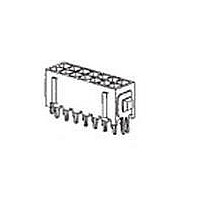
Power to the Board HDR VERT 20P 30 AU DUAL
Manufacturer
TE Connectivity
Type
Powerr
Specifications of 2-794632-0
Gender
HDR
Body Orientation
Straight
Housing Material
Nylon
Number Of Contacts
20POS
Number Of Ports
1Port
Number Of Terminals
20
Current Rating (max)
5/ContactA
Pitch (mm)
3mm
Contact Material
Brass
Operating Temp Range
-40C to 105C
Voltage Rating Max
250VAC
Mounting Style
Through Hole
Termination Method
Solder
Contact Plating
Gold
Product Height (mm)
9.24mm
Product Depth (mm)
8.67mm
Product Length (mm)
34mm
Product Type
Plug Housings
Number Of Positions / Contacts
20
Connector Type
Header
Mount Angle
Vertical
Mount
Printed Circuit Board
Pcb Mount Alignment
Without
Product Line
Micro MATE-N-LOK
Mating Retention Type
Latching
Voltage (vac)
250
Current Rating (a)
5
Termination Post Length (mm [in])
3.18 [0.125]
Solder Tail Contact Plating
Tin-Lead
Number Of Positions
20
Number Of Rows
2
Row-to-row Spacing (mm [in])
3.00 [0.118]
Centerline (mm [in])
3.00 [0.118]
Pcb Mount Retention Type
Compliant Posts
Mating Retention
With
Contact Type
Pin
Contact Termination Type
Through Hole
Contact Layout
Double-Row
Contact Plating, Mating Area, Material
Gold (30)
Contact Base Material
Brass
Connector Style
Plug
Housing Color
Black
Ul Flammability Rating
UL 94V-0
Rohs/elv Compliance
Not ELV/RoHS compliant
Lead Free Solder Processes
Not suitable for lead free processing
Applies To
Printed Circuit Board
Pcb Thickness, Recommended (mm [in])
1.57 [0.062]
Lead Free Status / RoHS Status
Not Compliant


Solderability, dip test.
Crimp tensile.
Vibration, random.
Mechanical shock.
Durability.
Header contact retention.
Crimp contact retention.
Rev D
Test Description
Solderable area shall have a
minimum of 95% solder coverage.
No discontinuities of 1 microsecond
or longer duration.
See Note.
No discontinuities of 1 microsecond
or longer duration.
See Note.
See Note.
Contact shall not dislodge.
See Note.
Contact shall not dislodge.
See Note.
Wire Size
(AWG)
20
22
24
26
28
30
Figure 1 (continued)
MECHANICAL
Requirement
(kg [lb] minimum)
Crimp Tensile
7.95 [17.5]
5.00 [11]
3.60 [7.9]
2.05 [4.5]
1.40 [3.1]
0.77 [1.7]
EIA-364-52,
Category 3 For thru-hole.
EIA-638 for surface mount.
Subject contacts to solderability.
EIA-364-8.
Determine crimp tensile at a
maximum rate of 25 ± 6 mm [.98 ±
.24 in] per minute.
EIA-364-28, Test Condition VII,
Condition D.
Subject mated specimens to 3.10
G's rms between 20-500 Hz. 15
minutes in each of 3 mutually
perpendicular planes.
See Figure 4.
EIA-364-27, Method A.
Subject mated specimens to 50 G's
half-sine shock pulses of 11
milliseconds duration. 3 shocks in
each direction applied along 3
mutually perpendicular planes, 18
total shocks.
See Figure 4.
EIA-364-9.
Mate and unmate specimens for 30
cycles for tin plated specimens, 75
cycles for 15 µin gold plated
specimens, and 150 cycles for 30
µin gold plated specimens at a
maximum rate of 500 cycles per
hour.
EIA-364-29.
Apply an axial load of 1.4 kg [3.1 lb]
to contacts at a rate of 0.45 kg [1 lb]
per second and hold for 6 seconds.
EIA-364-29.
Apply an axial load of 1.81 kg [4 lb]
to contacts at a rate of 0.45 kg [1 lb]
per second and hold for 6 seconds.
Procedure
108-1836
3 of 7
Related parts for 2-794632-0
Image
Part Number
Description
Manufacturer
Datasheet
Request
R

Part Number:
Description:
CONN FPC 22POS 1MM RT ANG SMD
Manufacturer:
TE Connectivity
Datasheet:

Part Number:
Description:
CONN FPC 26POS 1MM RT ANG SMD
Manufacturer:
TE Connectivity
Datasheet:
Part Number:
Description:
CONN FPC 23POS 1MM RT ANG SMD
Manufacturer:
TE Connectivity
Datasheet:
Part Number:
Description:
CONN FPC 25POS 1MM RT ANG SMD
Manufacturer:
TE Connectivity
Datasheet:

Part Number:
Description:
CONN FPC 20POS 1MM RT ANG SMD
Manufacturer:
Tyco Electronics
Datasheet:

Part Number:
Description:
Conn Shrouded Header HDR 20 POS 2.54mm Solder ST Thru-Hole
Manufacturer:
TE Connectivity
Datasheet:

Part Number:
Description:
Conn Shrouded Header HDR 20 POS 2.54mm Solder ST Thru-Hole
Manufacturer:
TE Connectivity
Datasheet:

Part Number:
Description:
Conn Shrouded Header HDR 20 POS 2.54mm Solder RA Thru-Hole
Manufacturer:
TE Connectivity
Datasheet:

Part Number:
Description:
Conn Ejector Header HDR 20 POS 2.54mm Solder RA Thru-Hole
Manufacturer:
TE Connectivity
Datasheet:

Part Number:
Description:
Manufacturer:
TE Connectivity
Datasheet:

Part Number:
Description:
FSM14JH=6MM TACT SWITCH HIGH TEMP
Manufacturer:
TE Connectivity
Datasheet:

Part Number:
Description:
IDC LOW PRO HDR 20P VERT LG LAT BLUE
Manufacturer:
TE Connectivity
Datasheet:

Part Number:
Description:
MQS STIFTE MAGZ
Manufacturer:
TE Connectivity
Datasheet:
Part Number:
Description:
V23061A1005A502=MINISTARKSTROM
Manufacturer:
TE Connectivity
Datasheet:

Part Number:
Description:
DISCRETE SOCKET, PC BOARD
Manufacturer:
TE Connectivity
Datasheet: