1766161-1 TE Connectivity, 1766161-1 Datasheet - Page 20
1766161-1
Manufacturer Part Number
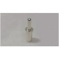
1766161-1
Description
CONTACT,PIN,#8 LOCK, #10 CRIMP BARREL
Manufacturer
TE Connectivity
Type
Contactr
Series
Elcon ICCONr
Specifications of 1766161-1
Body Orientation
Straight
Housing Material
Not Required
Number Of Contacts
1POS
Number Of Ports
1Port
Number Of Terminals
1
Pitch (mm)
Not Requiredmm
Contact Material
Brass
Mounting Style
Cable
Termination Method
Crimp
Contact Plating
Silver
Rohs Compliant
YES
Product Type
Contacts
Pin Or Socket
Pin
Contact Termination
Crimp
Wire Gauge
8-10 AWG
Contact Finish
Silver
Contact Finish Thickness
200µin (5.08µm)
Current Rating
35A
Product Line
ICCON
Wire/cable Type
Discrete Wire
Termination Method To Wire/cable
Crimp
Mating Post Length (mm [in])
11.94 [0.470]
Mating Retention Type
Lock
Contact - Rated Current (a)
35
Hot Pluggable
No
Operating Voltage Reference
AC
Operating Voltage (vac)
250
Wire/cable Size (awg)
8 – 10
Wire/cable Size (mm²)
5 – 8
Wire/cable Size (cma)
9,072.29 – 16,774.96
Profile Height (y-axis) (mm [in])
3.56 [0.140]
Mating Retention
With
Number Of Positions
1
Length (x-axis) (mm [in])
11.94 [0.470]
Width (z-axis) (mm [in])
7.62 [0.300]
Contact Type
Pin
Contact Base Material
Copper
Contact Plating, Mating Area, Material
Silver
Contact Plating, Mating Area, Thickness (µm [?in])
5.08 [200]
Contact Design
Screw Machined
Mating Alignment
Without
Ul Flammability Rating
UL 94V-0
Custom Configurable
No
Rohs/elv Compliance
RoHS compliant, ELV compliant
Lead Free Solder Processes
Not relevant for lead free process
Rohs/elv Compliance History
Always was RoHS compliant
Agency/standard
UL
Ul Rating
Recognized
Agency/standard Number
UL 1977
Ul Voltage Rating (vac)
250
Operating Temperature (°c [°f])
-40 – +105 [-40 – +221]
Applies To
Wire/Cable
Application Use
Wire-to-Board
Contact Transmits (typical Application)
Power
Pick And Place Cover
Without
Packaging Method
Bag
Lead Free Status / RoHS Status
Compliant


PCB-Mount
To create a unique configuration for MULTI-BEAM connectors simply complete this worksheet and forward it to your Tyco Electronics sales engineer.
1. Performance Grade
2. Application
3. Gender
4. Orientation
5. Termination
6. Termination Style
7. Mounting to PCB
8. Select # of Contacts
9. Additional Requirements
10. Customer Information
Catalog 1773096
Revised 2-10
www.tycoelectronics.com
Hold
Down
Section A: (Power Contacts)
Contact Centerline Spacings:
Section B: (Signal Contacts)
Section C: (Power Contacts)
Contact Centerline Spacings:
Name: __________________________ Company: ____________________ Location: ________________________
Phone: __________________________ Fax:
(Submit to your local Tyco Electronics Sales Engineer)
N
1
3
A
2
C
Header/Plug (Right-Angle Shown)
2
Receptacle (Vertical Shown)
N
1
1 2 3 4
Electrically Hot
D
C
B
A
N 5
B
Dimensions are in inches and
5
millimeters unless otherwise
specified. Values in brackets
are metric equivalents.
4
N
B
Cable Only
PCB Only
(Cable Only)
(PCB Only)
3
D
C
B
A
2 1
1
2
N
Power Connectors & Interconnection Systems
MULTI-BEAM XL and MULTI-BEAM XLE Connectors Custom Configuration Worksheet
3
C
MULTI-BEAM XL Connector
Board-to-Board
Plug (Male)
Hold Downs (one on either end)
.122
.150
3
___ Enter Power Contact Type (LP - Low Power, HP - High Power)
___ Enter # of Power Contacts (Loaded with standard length Power Contacts)
___ Enter the position(s) to be loaded with Pre-mate contact (Receptacles only)
___ Enter # of Signal Contacts (Multiples of 8 are standard, i.e. 16, 24, 32...)
___ Enter the positions with Post-Mate Contacts (Mate-Last-Break-First, Plugs only)
___ Enter Power Contact Type (LP - Low Power, HP - High Power)
___ Enter # of Power Contacts (Loaded with standard length Power Contacts)
___ Enter the positions to be loaded with Pre-Mate Contacts (Receptacles only)
A
4
2
′′
′′
(Mate-First-Break-Last) ( i.e. #1,#3, etc.)
Note: Row A is standard (i.e. A1, A3, etc.)
(Mate-First-Break-Last, i.e. #1, #3, etc.)
N
Power
Signal
[3.10 mm] Mounting holes (Accepts #4 screws, right-angle connectors only)
[3.81 mm] Mounting holes (Accepts #6 screws, right-angle connectors only)
1
Mounting
Hole
Solder Tail .135
Solder Tail .165
Blind-Mate specify Floating or Slide-to-Lock Receptacle
Right-Angle
Dimensions are shown for
reference purposes only.
Specifications subject
to change.
.200
.250
.300
.200
__________________________________
Cable-Mount
XYZ Floating
Slide-to-Lock
′′
′′
′′
′′
[5.08 mm] (HDP)
[5.08 mm] (for High Power only)
[6.35 mm] (for High Power only)
[7.62 mm] (for High Power only)
8 AWG
22 AWG
′′
′′
[3.43 mm]
[4.19 mm]
MULTI-BEAM XL, MULTI-BEAM XLE, TE (logo) and TYCO ELECTRONICS are
trademarks of the Tyco Electronics group of companies and its licensors.
USA: 1-800-522-6752
Canada: 1-905-470-4425
Mexico: 01-800-733-8926
C. America: 52-55-1106-0803
10 AWG
24 AWG
.250
′′
MULTI-BEAM XLE Connector
Cable-to-Board
Vertical
[6.35 mm] (P)
Press-Fit .120
Press-Fit .135
Press-Fit .165
Receptacle (Female)
e-mail:
Plugs
XYZ Floating
Squeeze-to-
Release
_
________________________
12 AWG
26 AWG
′′
′′
′′
South America: 55-11-2103-6000
Hong Kong: 852-2735-1628
Japan: 81-44-844-8013
UK: 44-(0)8002-67666
[3.05 mm]
[3.43 mm]
[4.19 mm]
.300
′′
[7.62 mm](ACP)
Latching
14 AWG
29
Related parts for 1766161-1
Image
Part Number
Description
Manufacturer
Datasheet
Request
R

Part Number:
Description:
Printers THERMAL PRINTER HS-SLEEVE MARKER
Manufacturer:
TE Connectivity


Part Number:
Description:
High Speed / Modular Connectors 30P HEADER ASSY
Manufacturer:
TE Connectivity
Datasheet:

Part Number:
Description:
High Speed / Modular Connectors REC 6X005P R/A LT B-PLANE HS3
Manufacturer:
TE Connectivity
Datasheet:

Part Number:
Description:
High Speed / Modular Connectors 2MM HM RCPT 50P R/A AU
Manufacturer:
TE Connectivity
Datasheet:

Part Number:
Description:
High Speed / Modular Connectors 2MM HM RCPT 50P R/A AU
Manufacturer:
TE Connectivity
Datasheet:


Part Number:
Description:
Manufacturer:
TE Connectivity
Datasheet:


Part Number:
Description:
Manufacturer:
TE Connectivity
Datasheet:

Part Number:
Description:
Manufacturer:
TE Connectivity
Datasheet:

Part Number:
Description:
Manufacturer:
TE Connectivity
Datasheet: