EVAL-ADAU1761Z Analog Devices Inc, EVAL-ADAU1761Z Datasheet - Page 3
EVAL-ADAU1761Z
Manufacturer Part Number
EVAL-ADAU1761Z
Description
Eval Board For ADAU1761
Manufacturer
Analog Devices Inc
Series
SigmaDSP®r
Specifications of EVAL-ADAU1761Z
Main Purpose
Audio, CODEC
Embedded
Yes, DSP
Utilized Ic / Part
ADAU1761
Primary Attributes
Stereo, 24-Bit, 8 ~ 96 kHz Sampling Rate, GUI Tool
Secondary Attributes
I²C and GPIO Interfaces, 2 Differential and 1 Stereo Single-Ended Analog Inputs and Outputs
Silicon Manufacturer
Analog Devices
Core Architecture
SigmaDSP
Silicon Core Number
ADAU1761
Silicon Family Name
SigmaDSP
Application Sub Type
Audio
Lead Free Status / RoHS Status
Lead free / RoHS Compliant
Available stocks
Company
Part Number
Manufacturer
Quantity
Price
Company:

Part Number:
EVAL-ADAU1761Z
Manufacturer:
Analog Devices Inc
Quantity:
135


SETTING UP THE EVALUATION BOARD—QUICK START
SigmaStudio SOFTWARE INSTALLATION
To install the SigmaStudio software, follow these steps:
1.
2.
3.
HARDWARE SETUP, USBi
To set up the USBi hardware, follow these steps:
1.
2.
3.
POWERING THE BOARD
The board can be powered either by the USBi or by an external
power supply. For the board to run independently from the
computer, disconnect Jumper J5 and connect the power supply
at J2. The power indicator LED D1 should now be lit.
CONNECTING AUDIO CABLES
In this example, the board is set up for stereo analog inputs and
stereo analog outputs, using 3.5 mm (1/8”) cables.
1.
2.
Open the provided .zip file and extract the files to your PC.
Alternately, insert the SigmaStudio CD into the PC optical
drive and locate the SigmaStudio folder on the CD.
If Microsoft® .NET Framework Version 2.0 is not already
installed on the PC, install it by double-clicking dotnetfx.exe.
Install SigmaStudio by double-clicking setup.exe and
following the prompts. A computer restart is not required.
Plug the USBi ribbon cable into Header J1.
Connect the USB cable to your computer and to the USBi.
When prompted for drivers, follow these steps:
a)
b) Choose Search for the best driver in these locations.
c)
d) The USBi driver is located in C:\Program Files\
e)
f)
g)
Connect the audio source to Input Jack J24.
Connect Output Jack J19 to your headphones.
Choose Install from a list or a specific location.
Check the box for Include this location in the search.
Analog Devices Inc\Sigma Studio\USB drivers.
Click Next.
If prompted to choose a driver, select CyUSB.sys.
If the PC is running Windows® XP and you receive the
message that the software has not passed Windows
Logo testing, click Continue Anyway.
Rev. 0 | Page 3 of 12
SWITCH AND JUMPER SETTINGS
To configure the board for stereo analog input and output, make
sure that the switches and jumpers are set as follows (see Figure 2).
•
•
•
•
•
•
The ADAU1761 uses the on-board oscillator as a master
clock source (S5 switched to OSC).
Regulator output VDD is set for 3.3 V operation
(S1 switched to 3.3 V).
Power is supplied by USB (J5 is connected with a jumper).
AVDD is connected to VDD (J17 connected).
IOVDD and AVDD operate at VDD (J16 connected).
I
2
C control mode is hardwired on board.
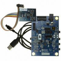
Figure 2. Evaluation Board Setup and Configuration
EVAL-ADAU1761Z
Related parts for EVAL-ADAU1761Z
Image
Part Number
Description
Manufacturer
Datasheet
Request
R


Part Number:
Description:
BOARD EVAL FOR SI270X-A
Manufacturer:
Silicon Laboratories Inc
Datasheet:

Part Number:
Description:
BUCK CONV REF DESIGN KIT IP1201
Manufacturer:
International Rectifier
Datasheet:
Part Number:
Description:
BOARD DEMO SYNC DUAL BUCK CNVTER
Manufacturer:
International Rectifier
Datasheet:
Part Number:
Description:
BOARD DEMO SYNC BUCK CONVETER
Manufacturer:
International Rectifier
Datasheet:

Part Number:
Description:
EVALBOARD/EB Omnidirectional microphone - Analog
Manufacturer:
Analog Devices
Datasheet:
Part Number:
Description:
EVALBOARD/EB Omnidirectional microphone - Analog
Manufacturer:
Analog Devices
Datasheet:


Part Number:
Description:
BOARD EVAL LED DRIVER LT3756
Manufacturer:
Linear Technology
Datasheet:

Part Number:
Description:
BOARD EVAL FOR AD7741/7742
Manufacturer:
Analog Devices Inc
Datasheet:

Part Number:
Description:
±1.7g Dual-Axis IMEMS Accelerometer Evaluation Board
Manufacturer:
Analog Devices Inc
Datasheet:

Part Number:
Description:
IC MULTIPLIER ANALOG 8-SOIC T/R
Manufacturer:
Analog Devices Inc
Datasheet:

Part Number:
Description:
IC ANALOG MULTIPLIER 8-DIP
Manufacturer:
Analog Devices Inc
Datasheet:
Part Number:
Description:
IC ANALOG MULTIPLIER 8-SOIC
Manufacturer:
Analog Devices Inc
Datasheet:
Part Number:
Description:
IC ANALOG MULTIPLIER 8-DIP
Manufacturer:
Analog Devices Inc
Datasheet: