EVAL-ADT7X10EBZ Analog Devices Inc, EVAL-ADT7X10EBZ Datasheet - Page 4
EVAL-ADT7X10EBZ
Manufacturer Part Number
EVAL-ADT7X10EBZ
Description
Evaluation Board I.c.
Manufacturer
Analog Devices Inc
Specifications of EVAL-ADT7X10EBZ
Sensor Type
Temperature
Sensing Range
-55°C ~ 150°C
Interface
I²C
Sensitivity
±0.5°C
Voltage - Supply
2.7 V ~ 5.5 V
Embedded
No
Utilized Ic / Part
ADT7410
Silicon Manufacturer
Analog Devices
Silicon Core Number
ADT7410
Kit Application Type
Sensing - Temperature
Application Sub Type
Temperature Sensor
Lead Free Status / RoHS Status
Lead free / RoHS Compliant
Other names
EVAL-ADT7410EBZ
EVAL-ADT7410EBZ
EVAL-ADT7410EBZ


UG-047
EVALUATION BOARD HARDWARE
CONNECTORS ON THE MAIN BOARD
J1
J1 is a mini-USB socket. Connect the USB cable to this socket.
The USB signals, D+ and D−, along with power and ground for
the evaluation board, are connected to this socket.
J2
This connector is a 10-pin terminal block connector. It provides
access to the ADT7310/ADT7410 serial interface, interrupt, and
GPIO signals, as well as to the power and ground signals.
Table 1. J2 Connector Signals
J2 Pin
1
2
3
4
5
6
7
8
9
10
Note that Pin 3 and Pin 4 are labeled incorrectly on the PCB;
the correct pinout is listed in Table 1.
CONNECTORS ON THE SECONDARY BOARD
J1
There is no connector mounted, but connections can be made
to the ADT7410 on the secondary board at this location.
Table 2. J1 Connector Signals
J1 Pin
1
2
3
4
5
6
J3
There is no connector mounted, but connections can be made
to the ADT7310 on the secondary board at this location.
Signal
DIN
Signal
VCC
GND
SDA
SCL
A0
A1
SCLK
DOUT
CSE
VCC
GND
SCL
SDA
A0
A1
Rev. 0 | Page 4 of 12
Table 3. J3 Connector Signals
J3 Pin
1
2
3
4
5
6
INDICATOR LEDS
There are four indicator LEDs on the ADT7310/ADT7410 main
evaluation board and two LEDs on the secondary board. If an
LED is illuminated, the corresponding signal is active.
Table 4. Indicator LEDs—Main Board
LED
D1
D2
D3
D4
Table 5. Indicator LEDs—Secondary Board
LED
D1
D2
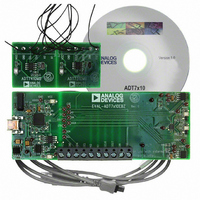
CONNECTING THE SECONDARY BOARD TO THE
MAIN EVALUATION BOARD
You can use the evaluation board software to evaluate the
sensors on the secondary board. Connect the interfaces on
Connector J1 (for the ADT7410) and Connector J3 (for the
ADT7310) of the secondary interface to Connector J2 on the
main evaluation board. Ensure that all communication wires are
connected securely from J1 and J3 to J2 on the main board.
For the ADT7410, the A0 and A1 pins are address pins. The
evaluation software assumes that the external ADT7410 has A0
connected high and A1 connected low. A0 on the secondary
board must be connected directly to V
board. Do not connect A0 from the secondary board to the
main board because doing so would prevent communications
between the two boards.
Note that on the main board SDA and SCL are labeled incorrectly.
See Table 1 for the correct pinout of the Main Board Connector J2.
Signal
3.3 V
INT
CT
3 V
Signal
ADT7410 V
ADT7310 V
Evaluation Board User Guide
Signal
VCC
GND
SCLK
DOUT
DIN
CSE
DD
DD
Color
Green
Red
Red
Green
Color
Green
Green
DD
on the secondary
Related parts for EVAL-ADT7X10EBZ
Image
Part Number
Description
Manufacturer
Datasheet
Request
R


Part Number:
Description:
BOARD EVAL FOR SI270X-A
Manufacturer:
Silicon Laboratories Inc
Datasheet:

Part Number:
Description:
BUCK CONV REF DESIGN KIT IP1201
Manufacturer:
International Rectifier
Datasheet:
Part Number:
Description:
BOARD DEMO SYNC DUAL BUCK CNVTER
Manufacturer:
International Rectifier
Datasheet:
Part Number:
Description:
BOARD DEMO SYNC BUCK CONVETER
Manufacturer:
International Rectifier
Datasheet:

Part Number:
Description:
EVALBOARD/EB Omnidirectional microphone - Analog
Manufacturer:
Analog Devices
Datasheet:
Part Number:
Description:
EVALBOARD/EB Omnidirectional microphone - Analog
Manufacturer:
Analog Devices
Datasheet:


Part Number:
Description:
BOARD EVAL LED DRIVER LT3756
Manufacturer:
Linear Technology
Datasheet:

Part Number:
Description:
BOARD EVAL FOR AD7741/7742
Manufacturer:
Analog Devices Inc
Datasheet:

Part Number:
Description:
±1.7g Dual-Axis IMEMS Accelerometer Evaluation Board
Manufacturer:
Analog Devices Inc
Datasheet:

Part Number:
Description:
IC MULTIPLIER ANALOG 8-SOIC T/R
Manufacturer:
Analog Devices Inc
Datasheet:

Part Number:
Description:
IC ANALOG MULTIPLIER 8-DIP
Manufacturer:
Analog Devices Inc
Datasheet:
Part Number:
Description:
IC ANALOG MULTIPLIER 8-SOIC
Manufacturer:
Analog Devices Inc
Datasheet:
Part Number:
Description:
IC ANALOG MULTIPLIER 8-DIP
Manufacturer:
Analog Devices Inc
Datasheet: