A1361LKTTN-T Allegro Microsystems Inc, A1361LKTTN-T Datasheet - Page 16
A1361LKTTN-T
Manufacturer Part Number
A1361LKTTN-T
Description
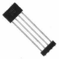
IC,HALL-EFFECT SENSOR,SINGLE-ENDED,BICMOS,SIP,4PIN,PLASTIC
Manufacturer
Allegro Microsystems Inc
Type
Linear - Unipolar, Bipolarr
Datasheet
1.A1360LKTTN-T.pdf
(25 pages)
Specifications of A1361LKTTN-T
Sensing Range
1.4mV/G ~ 4.5mV/G
Voltage - Supply
4.5 V ~ 5.5 V
Current - Supply
12mA
Current - Output (max)
10mA
Output Type
Analog, Ratiometric
Features
Programmable
Operating Temperature
-40°C ~ 150°C
Package / Case
4-SIP
Lead Free Status / RoHS Status
Lead free / RoHS Compliant
Other names
620-1234-2


A1360, A1361,
and A1362
Parameter Selection
Each of the four programmable parameters can be accessed
through its corresponding parameter register. These registers are
located in two distinct zones in the A136x devices:
Zone 1, Register 1:
• Fine sensitivity, Sens
Zone 2, Register 1:
• Fine quiescent voltage output, V
Zone 2, Register 2:
• Coarse quiescent voltage output, V
• Overall device locking, LOCK
To select the register in the first zone, a sequence of one V
pulse, the key for the register, and a second V
VCC supply interruptions) must be applied serially to the VOUT
pin. The pulse train used for selection of the first register, key 1,
is shown in figure 1.
After the falling edge of the second V
selected register may be addressed with the appropriate code (see
Bit Field Addressing section, below).
The first zone must be traversed before the second zone can be
accessed. After completing any bit field addressing in the first
zone, to enter the second zone, apply a third V
the first zone, this must be followed by the key for the parameter
register, then a V
supply interruptions).
Bit Field Addressing
After the register of a programmable parameter has been selected
as described above, the code pulses must be applied serially to
Figure 1. Voltage pulse sequence required to select the first
programmable register in the first zone.
PH
V
V
V
P(HIGH)
P(LOW)
P(MID)
pulse and the bit field code (with no VCC
V+
0
t
LOW
OUT(Q)
Adjustable Bandwidth (50 kHz Maximum) and Analog Output
Low-Noise Programmable Linear Hall Effect Sensor ICs with
OUT(Q)
PH
t
ACTIVE
pulse, the bit field of the
PH
PH
Programming Procedures
pulse (with no
pulse. As in
PH
the VOUT pin with no VCC supply interruptions. As each addi-
tional pulse in the code is transmitted, the overall setting of the
bit field increments by 1, up to the maximum possible code for
that register (see the Programming Logic table). The A136x logic
interprets the overall setting (the binary sum of all of the acti-
vated or blown fuses) and applies it to the value of the parameter,
according to the step size for the parameter (shown in the Electri-
cal Characteristics table).
Addressing activates the corresponding fuse locations in the
given bit field by incrementing the binary value of an internal
DAC. Measurements can be taken after each pulse to determine
if the desired result for the programmable parameter has been
reached. Cycling the supply voltage resets all the locations in the
bit field that have unblown fuses to their initial states.
Figure 2. Bit fi eld addressing pulse train. Addressing the bit fi eld by incre-
menting the code causes the programmable parameter value to change.
The number of bits available for a given programming code, n, varies
among parameters; for example, the bit fi eld for Sensitivity has 8 bits avail-
able, which allows 255 separate codes to be used.
Fuse Blowing
After the required code is found for a given parameter, its value
can be set permanently by blowing individual fuses in the appro-
priate register bit field. Blowing is accomplished by applying a
high voltage pulse, called a blow pulse, of sufficient duration to
permanently set an addressed bit by blowing a fuse internal to the
device. Due to power requirements, the fuse for each bit in the
bit field must be blown individually. To accomplish this, the code
representing the desired parameter value must be translated to a
binary number. For example, as shown in figure 3, decimal code
5 is equivalent to the binary number 101. Therefore bit 2 (code
4) must be addressed and blown, the device power supply cycled,
and then bit 0 (code 1) addressed and blown. The order of blow-
ing bits, however, is not important. Blowing bit 0 first, and then
bit 2, is acceptable.
V
V
P(LOW)
P(MID)
V+
0
t
ACTIVE
115 Northeast Cutoff
1.508.853.5000; www.allegromicro.com
Allegro MicroSystems, Inc.
Worcester, Massachusetts 01615-0036 U.S.A.
t
LOW
16
Related parts for A1361LKTTN-T
Image
Part Number
Description
Manufacturer
Datasheet
Request
R

Part Number:
Description:
CONN RECEPT CPC 4POS REV SER 1
Manufacturer:
Tyco Electronics
Datasheet:

Part Number:
Description:
IC, HALL EFFECT SENSOR, Linear, SOIC-8
Manufacturer:
Allegro Microsystems Inc
Datasheet:
Part Number:
Description:
IC, HALL EFFECT SENSOR, Linear, SOIC-8
Manufacturer:
Allegro Microsystems Inc
Datasheet:
Part Number:
Description:
IC, HALL EFFECT SENSOR, Linear, SOIC-8
Manufacturer:
Allegro Microsystems Inc
Datasheet:

Part Number:
Description:
IC SWITCH INTERFACE 2CHAN 8-SOIC
Manufacturer:
Allegro Microsystems Inc
Datasheet:

Part Number:
Description:
IC SMOKE DETECTOR ION 16-DIP
Manufacturer:
Allegro Microsystems Inc
Datasheet:
Part Number:
Description:
IC SMOKE DETECTOR ION 16-DIP
Manufacturer:
Allegro Microsystems Inc
Datasheet:
Part Number:
Description:
IC SMOKE DETECTOR ION 16-DIP
Manufacturer:
Allegro Microsystems Inc
Datasheet:
Part Number:
Description:
IC SMOKE DETECTOR PHOTO 16-DIP
Manufacturer:
Allegro Microsystems Inc
Datasheet:
Part Number:
Description:
IC SMOKE DETECTOR ION 16-DIP
Manufacturer:
Allegro Microsystems Inc
Datasheet:
Part Number:
Description:
IC SMOKE DETECTOR PHOTO 16-DIP
Manufacturer:
Allegro Microsystems Inc
Datasheet:
Part Number:
Description:
IC SMOKE DETECTOR PHOTO 16-DIP
Manufacturer:
Allegro Microsystems Inc
Datasheet:
Part Number:
Description:
IC SMOKE DETECTOR ION 16-DIP
Manufacturer:
Allegro Microsystems Inc
Datasheet:
Part Number:
Description:
IC SMOKE DETECTOR PHOTO 16-SOIC
Manufacturer:
Allegro Microsystems Inc
Datasheet:

Part Number:
Description:
IC LED DRIVER HIGH BRIGHT 16-QFN
Manufacturer:
Allegro Microsystems Inc
Datasheet: