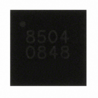
A8504EECTR-T Allegro Microsystems Inc, A8504EECTR-T Datasheet - Page 13

A8504EECTR-T
Manufacturer Part Number
A8504EECTR-T
Description
IC,Laser Diode/LED Driver,LLCC,28PIN,PLASTIC
Manufacturer
Allegro Microsystems Inc
Type
Backlight, White LED, RGBr
Datasheet
1.A8504EECTR-T.pdf
(18 pages)
Specifications of A8504EECTR-T
Topology
PWM, Step-Up (Boost)
Number Of Outputs
8
Internal Driver
Yes
Type - Primary
Backlight
Type - Secondary
RGB, White LED
Frequency
200kHz ~ 2MHz
Voltage - Supply
4.2 V ~ 5.5 V
Voltage - Output
47V
Mounting Type
Surface Mount
Package / Case
26-WFQFN Exposed Pad
Operating Temperature
-40°C ~ 85°C
Current - Output / Channel
45mA
Internal Switch(s)
Yes
Lead Free Status / RoHS Status
Lead free / RoHS Compliant
Efficiency
-
Lead Free Status / RoHS Status
Lead free / RoHS Compliant
Other names
620-1215-2
Available stocks
Company
Part Number
Manufacturer
Quantity
Price
Company:
Part Number:
A8504EECTR-T
Manufacturer:
HONGFA
Quantity:
20 000
A8504
Typical Application Circuits
A typical application circuit for dimming an LCD monitor back-
light with multiple LED strings is shown in figure 1. Figure 8
shows two dimming methods: digital PWM control (PWM signal
on the PWM pin) and analog PWM control, with the
nal, V
The current flowing through RA can be calculated as:
This current changes the reference current, I
LED current can be changed by changing V
changed in the range from 40 μA to 100 μA.
Application Circuit for 1000:1 Dimming Level
A wider dimming range can be achieved by changing the refer-
ence current, I
current levels turn on Q1. R
level. This current level can be set to 45 mA, and then it can be
dimmed by applying 100% to 0.25% duty cycle on the PWM pin.
The reference current can be reduced by turning off Q1. LED
current can be dimmed to 18 mA by reducing reference current
through ISET pin. This provides 1000:1 combined dimming level
range. Figure 10 shows the accuracy, Err
circuit.
A
, applied to the ISET pin through a resistor, RA.
SET
I
SET
, while using PWM dimming. For higher output,
= V
SET
Figure 8. Typical application circuit for PWM dimming, using digital PWM (on the PWM pin).
C
C
/ R
I
A
ISET
SET
= V
RFSET
V
and R
A
A
– (V
RISET
/ R
RA
A
A
WLED/RGB Backlight Driver for Medium Size LCDs
ISETP
.
– V
V
5 V ±10%
LEDX
IN
SET
A
set the 100% current
SET
. I
) / R
, results using this
LED3 LED5 LED7 LGND
SET
PWM
SKIP
COMP
FSET
ISET
LED1
, as follows:
C
IN
A
.
can be
analog sig-
VIN
V
24 V
BAT
A8504
SW SW
LED8 LED6 LED4
Figure 9. Configuration for 1000:1 dimming.
Figure 10. Typical accuracy, normalized to the 100% current level,
versus dimming level, with F
ROVP
100
OVP
95
90
85
80
75
AGND
PGND
SEL3
SEL2
SEL1
LED2
GND
0.1
COUT
V
V
OUT
IN
RISETP
Q1
RISET
1.0
Dimming Level (%)
115 Northeast Cutoff
1.508.853.5000; www.allegromicro.com
Allegro MicroSystems, Inc.
Worcester, Massachusetts 01615-0036 U.S.A.
PWM
ISET
= 100 Hz.
10.0
100.0
13


