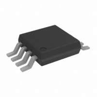
AD7418ARMZ Analog Devices Inc, AD7418ARMZ Datasheet - Page 2

AD7418ARMZ
Manufacturer Part Number
AD7418ARMZ
Description
1CH. I2C ADC W/ON-CHIP TEMP SENSOR I.C.
Manufacturer
Analog Devices Inc
Datasheet
1.AD7418ARZ.pdf
(24 pages)
Specifications of AD7418ARMZ
Function
Temp Monitoring System (Sensor)
Topology
ADC, Comparator, Register Bank
Sensor Type
Internal
Sensing Temperature
-40°C ~ 125°C
Output Type
I²C™
Output Alarm
No
Output Fan
Yes
Voltage - Supply
2.7 V ~ 5.5 V
Operating Temperature
-40°C ~ 125°C
Mounting Type
Surface Mount
Package / Case
8-TSSOP, 8-MSOP (0.118", 3.00mm Width)
Number Of Elements
1
Resolution
10Bit
Architecture
SAR
Input Polarity
Unipolar
Input Type
Voltage
Rated Input Volt
2.5V
Differential Input
No
Power Supply Requirement
Single
Single Supply Voltage (typ)
3.3/5V
Single Supply Voltage (min)
2.7V
Single Supply Voltage (max)
5.5V
Dual Supply Voltage (typ)
Not RequiredV
Dual Supply Voltage (min)
Not RequiredV
Dual Supply Voltage (max)
Not RequiredV
Power Dissipation
450mW
Differential Linearity Error
±1LSB
Integral Nonlinearity Error
±1LSB
Operating Temp Range
-40C to 125C
Operating Temperature Classification
Automotive
Mounting
Surface Mount
Pin Count
8
Package Type
MSOP
Input Signal Type
Single-Ended
Lead Free Status / RoHS Status
Lead free / RoHS Compliant
For Use With
EVAL-AD7416/7/8EBZ - BOARD EVALUATION FOR AD7416/7/8
Lead Free Status / Rohs Status
Compliant
Available stocks
Company
Part Number
Manufacturer
Quantity
Price
Company:
Part Number:
AD7418ARMZ
Manufacturer:
ST
Quantity:
6 219
Part Number:
AD7418ARMZ
Manufacturer:
ADI/亚德诺
Quantity:
20 000
Part Number:
AD7418ARMZ-REEL
Manufacturer:
ADI/亚德诺
Quantity:
20 000
Company:
Part Number:
AD7418ARMZ-REEL7
Manufacturer:
MAXIM
Quantity:
1 480
Part Number:
AD7418ARMZ-REEL7
Manufacturer:
ADI/亚德诺
Quantity:
20 000
AD7416/AD7417/AD7418
TABLE OF CONTENTS
Features .............................................................................................. 1
Applications....................................................................................... 1
General Description ......................................................................... 1
Functional Block Diagrams............................................................. 1
Revision History ............................................................................... 2
Product Highlights ........................................................................... 3
Specifications..................................................................................... 4
Absolute Maximum Ratings............................................................ 7
Pin Configurations and Function Descriptions ........................... 8
Terminology .................................................................................... 10
Theory of Operation ...................................................................... 11
REVISION HISTORY
11/10—Rev. H to Rev. I
Changes to Figure 19...................................................................... 16
2/09—Rev. G to Rev. H
Updated Format..................................................................Universal
Changes to Data Sheet Title, Figure 2 and Figure 3..................... 1
Moved Product Highlights Section................................................ 3
Changes to Table 1............................................................................ 4
Changes to Endnote 1, Table 2........................................................ 6
Added Figure 5 Caption................................................................... 7
Changes to Table 4............................................................................ 8
Changes to Table 5 and Table 6....................................................... 9
Changes to On-Chip Reference Section...................................... 11
Changes to Figure 13...................................................................... 12
Changes to Table 8 and Table 10................................................... 13
Changes to Figure 15, Figure 16, and Figure 17 ......................... 15
Changes to Reading Data From the AD7416/AD7417/AD7418
Section, Figure 18, and Figure 19 ................................................. 16
Change to Mode 1 .......................................................................... 17
Changes to Figure 22 Caption and CONVST Pin Mode
Section.............................................................................................. 18
Moved Figure 21 and Figure 22 .................................................... 18
Changes to Power-On Reset Section............................................ 19
Updated Outline Dimensions ....................................................... 21
Changes to Ordering Guide .......................................................... 23
AD7417/AD7418 Specifications................................................. 4
AD7416 Specifications................................................................. 6
ESD Caution.................................................................................. 7
Circuit Information.................................................................... 11
Converter Details........................................................................ 11
Typical Connection Diagram ................................................... 11
Analog Inputs.............................................................................. 11
Rev. I | Page 2 of 24
Applications Information .............................................................. 19
Outline Dimensions ....................................................................... 21
8/04—Data Sheet Changed from Rev. F to Rev. G
Changes to Figure 12...................................................................... 12
Changes to Reading Data from the AD7416/AD7417/AD7418
Section.............................................................................................. 13
Changes to Power-On-Reset section ........................................... 14
7/03—Data Sheet Changed from Rev. E to Rev. F
Updated Features...............................................................................1
Updated Specifications .....................................................................3
Updated Absolute Maximum Ratings ............................................6
Updated Ordering Guide .................................................................6
Updated Product Highlights............................................................7
Updated Circuit Information...........................................................7
Updated Temperature Measurement section ................................9
10/02—Data Sheet Changed from Rev. D to Rev. E
Edits to Specifications Headings .....................................................2
Added Temperature Measurement section....................................8
Edits to Serial Bus Address section .............................................. 10
Edits to Figure 11............................................................................ 12
Edits to CONVST Pin Mode section ........................................... 14
Edits to Power-On-Reset section ................................................. 14
Addition of Figures 16 and 17 ...................................................... 15
Updated Outlines ........................................................................... 16
On-Chip Reference .................................................................... 11
Temperature Measurement ....................................................... 12
Internal Register Structure........................................................ 12
Serial Bus Interface..................................................................... 14
OTI Output ................................................................................. 17
Fault Queue ................................................................................. 17
Power-On Defaults..................................................................... 17
Operating Modes........................................................................ 17
CONVST Start Mode................................................................. 18
Supply Decoupling ..................................................................... 19
Power-On Reset.......................................................................... 19
Mounting the AD7416/AD7417/AD7418 .............................. 19
Fan Controller............................................................................. 19
Thermostat .................................................................................. 19
System with Multiple AD7416 Devices................................... 20
Ordering Guide .......................................................................... 23


