AD9230-250EBZ Analog Devices Inc, AD9230-250EBZ Datasheet - Page 9
AD9230-250EBZ
Manufacturer Part Number
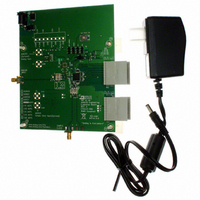
AD9230-250EBZ
Description
12-Bit 250 Msps ADC EB
Manufacturer
Analog Devices Inc
Datasheet
1.AD9230BCPZ-170.pdf
(32 pages)
Specifications of AD9230-250EBZ
Number Of Adc's
1
Number Of Bits
12
Sampling Rate (per Second)
250M
Data Interface
Serial
Inputs Per Adc
1 Single Ended
Input Range
1.0 ~ 1.5 V
Power (typ) @ Conditions
434mW @ 250MSPS
Voltage Supply Source
Single Supply
Operating Temperature
-40°C ~ 85°C
Utilized Ic / Part
AD9230
Lead Free Status / RoHS Status
Lead free / RoHS Compliant
Lead Free Status / RoHS Status
Lead free / RoHS Compliant


PIN CONFIGURATIONS AND FUNCTION DESCRIPTIONS
Table 7. Single Data Rate Mode Pin Function Descriptions
Pin No.
30, 32 to 34, 37 to 39,
41 to 43, 46
7, 24, 47
0
8, 23, 48
35
36
40
44
45
31
28
25
26
27
29
49
50
51
52
53
54
55
56
1
2
3
4
Mnemonic
AVDD
DRVDD
AGND
DRGND
VIN+
VIN−
CML
CLK+
CLK−
RBIAS
RESET
SDIO/DCS
SCLK/DFS
CSB
PWDN
DCO−
DCO+
D0−
D0+
D1−
D1+
D2−
D2+
D3−
D3+
D4−
D4+
1
1
DRGND
DRVDD
D3–
D3+
D4–
D4+
D5–
D5+
D6–
D6+
D7–
D7+
D8–
D8+
Description
1.8 V Analog Supply.
1.8 V Digital Output Supply.
Analog Ground.
Digital Output Ground.
Analog Input—True.
Analog Input—Complement.
Common-Mode Output Pin. Enabled through the SPI, this pin provides a reference for the
optimized internal bias voltage for VIN+/VIN−.
Clock Input—True.
Clock Input—Complement.
Set Pin for Chip Bias Current. (Place 1% 10 kΩ resistor terminated to ground.) Nominally 0.5 V.
CMOS-Compatible Chip Reset (Active Low).
Serial Port Interface (SPI®) Data Input/Output (Serial Port Mode); Duty Cycle Stabilizer Select
(External Pin Mode).
Serial Port Interface Clock (Serial Port Mode); Data Format Select Pin (External Pin Mode).
Serial Port Chip Select (Active Low).
Chip Power-Down.
Data Clock Output—Complement.
Data Clock Output—True.
D0 Complement Output Bit (LSB).
D0 True Output Bit (LSB).
D1 Complement Output Bit.
D1 True Output Bit.
D2 Complement Output Bit.
D2 True Output Bit.
D3 Complement Output Bit.
D3 True Output Bit.
D4 Complement Output Bit.
D4 True Output Bit.
10
11
12
13
14
1
2
3
4
5
6
7
8
9
PIN 0 (EXPOSED PADDLE) = AGND
Figure 4. Single Data Rate Mode
PIN 1
INDICATOR
Rev. 0 | Page 9 of 32
(Not to Scale)
AD9230
TOP VIEW
42 AVDD
41 AVDD
40 CML
39 AVDD
38 AVDD
37 AVDD
36 VIN–
35 VIN+
34 AVDD
33 AVDD
32 AVDD
31 RBIAS
30 AVDD
29 PWDN
AD9230
Related parts for AD9230-250EBZ
Image
Part Number
Description
Manufacturer
Datasheet
Request
R

Part Number:
Description:
12-Bit 170 Msps ADC EB
Manufacturer:
Analog Devices Inc
Datasheet:
Part Number:
Description:
12-Bit 210 Msps ADC EB
Manufacturer:
Analog Devices Inc
Datasheet:

Part Number:
Description:
±1.7g Dual-Axis IMEMS Accelerometer Evaluation Board
Manufacturer:
Analog Devices Inc
Datasheet:
Part Number:
Description:
Inertial Sensor Evaluation System
Manufacturer:
Analog Devices Inc
Datasheet:
Part Number:
Description:
Manufacturer:
Analog Devices Inc
Datasheet:
Part Number:
Description:
Manufacturer:
Analog Devices Inc
Datasheet:
Part Number:
Description:
Manufacturer:
Analog Devices Inc
Datasheet:
Part Number:
Description:
Manufacturer:
Analog Devices Inc
Datasheet:
Part Number:
Description:
Manufacturer:
Analog Devices Inc
Datasheet:
Part Number:
Description:
Manufacturer:
Analog Devices Inc
Datasheet:
Part Number:
Description:
Manufacturer:
Analog Devices Inc
Datasheet:
Part Number:
Description:
Manufacturer:
Analog Devices Inc
Datasheet:
Part Number:
Description:
Manufacturer:
Analog Devices Inc
Datasheet: