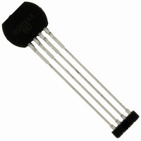
ATS667LSGTN-T Allegro Microsystems Inc, ATS667LSGTN-T Datasheet - Page 4

ATS667LSGTN-T
Manufacturer Part Number
ATS667LSGTN-T
Description
3-WIRE TRUE 0-SPEED HI ACCURACY GTS
Manufacturer
Allegro Microsystems Inc
Type
Special Purposer
Datasheet
1.ATS667LSGTN-T.pdf
(14 pages)
Specifications of ATS667LSGTN-T
Sensing Range
70% of Air Gap Trip, 30% of Air Gap Release
Voltage - Supply
4 V ~ 24 V
Current - Supply
12mA
Current - Output (max)
25mA
Output Type
Digital, Open Collector
Features
Gear Tooth Type
Operating Temperature
-40°C ~ 150°C
Package / Case
4-SIP
Operating Supply Voltage (min)
4V
Operating Supply Voltage (typ)
5/9/12/15/18V
Operating Supply Voltage (max)
24V
Output Current
20mA
Package Type
SIP Module(SG)
Pin Count
4
Mounting
Through Hole
Operating Temp Range
-40C to 150C
Operating Temperature Classification
Automotive
Lead Free Status / RoHS Status
Lead free / RoHS Compliant
Lead Free Status / RoHS Status
Lead free / RoHS Compliant
Other names
620-1328-2
ATS667LSG
OPERATING CHARACTERISTICS (continued)
Switchpoint Characteristics
Operational Speed
Bandwidth
Operate Point
Release Point
Running Mode Lockout Enable (LOE)
Running Mode Lockout Release (LOR)
1
minimum limits.
2
3
4
5
6
7
independently characterized. The field available from the Allegro 60-0 reference target is given in the reference target parameter section.
8
because the lowest signal-to-noise ratio for the V
will also occur at elevated temperatures.
9
Typical data is at V
1 G (gauss) = 0.1 mT (millitesla).
The device compensates for magnetic and installation offsets. Offsets greater than specification in gauss may cause inaccuracies in the output.
For power-on S
Operational Air Gap Range is dependent on the available magnetic field. The available field is target geometry and material dependent and should be
The repeatability specification is based on statistical evaluation of a sample population, evaluated at 1000 Hz. Repeatability is measured at 150°C
Single maximum allowable air gap change in outward direction (increase in air gap).
Maximum voltage must be adjusted for power dissipation and junction temperature; see Power Derating section.
Power-On Time is the time required to complete the internal Automatic Offset Adjust; the DACs are then ready for peak acquisition.
Characteristics
ROT
CC
≤ 200 rpm, edges are sensed target mechanical edges (see figure Definitions of Terms for Switchpoints).
= 12 V and T
a
b
Sensed Edge: leading (rising) mechanical edge in forward rotation, trailing (falling) mechanical edge in reverse rotation
B
OP(FWD)
+B
–B
+V
–V
triggers the output transition during forward rotation, and B
A
V
V
PROC(BOP)
PROC(BRP)
= 25°C, unless otherwise noted. Performance may vary for individual units, within the specified maximum and
True Zero-Speed, High Accuracy Gear Tooth Sensor IC
V
V
Symbol
LOE(RM)
LOR(RM)
S
f
Reverse
B
B
-3dB
ROT
OP
RP
B
PROC
OP(FWD)
B
OP
%
signal occurs at elevated temperatures. Therefore, the worst-case repeatability for the device
Definitions of Terms for Switchpoints
Allegro 60–0 Reference Target
Cutoff frequency for low-pass filter
% of peak-to-peak V
PDAC to NDAC, AG < AG
% of peak-to-peak V
PDAC to NDAC, AG < AG
V
disabled
V
enabled
b
PROC(PK-PK)
PROC(PK-PK)
Valid over operating voltage and temperature ranges; unless otherwise noted
Forward
Sensed Edge
< V
< V
B
Test Conditions
LOE(RM)
LOR(RM)
OP(REV)
PROC
PROC
B
OP(REV)
RP(FWD)
b
a
= output switching
= output switching
referenced from
max
referenced from
max
triggers the output transition during reverse rotation
, V
, V
Tooth
OUT
OUT
high to low
low to high
Valley
B
RP(REV)
B
115 Northeast Cutoff
1.508.853.5000; www.allegromicro.com
Allegro MicroSystems, Inc.
Worcester, Massachusetts 01615-0036 U.S.A.
Min.
RP
15
0
–
–
–
–
%
t
100 %
Typ.
100
220
20
70
30
–
1
12000
Max.
–
–
–
–
–
Unit
kHz
rpm
mV
mV
%
%
4


